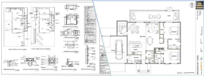
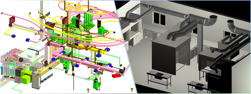
Today’s post covers architectural construction drawings and how companies apply them in their projects. The term “construction” evokes vivid images, from hard-hat-clad workers to the hustle and bustle of material transfer between various points. But as far as construction is concerned, you might think of construction drawings or plans. For novice eyes, these drawings and plans might look completely alien, incomprehensible, and impossible to understand. However, if you ask any freelance construction drawings and CAD drafting and design professionals, they will tell you that a construction drawing is always the first step in any construction process.
Freelance architectural construction drawings are among the most fundamental things you need before you begin the construction of your structure. These construction drawings are used in architectural and construction activities and projects for various applications and reasons. This post will give you a walkthrough of the different types of architectural construction drawings and how companies use them.
RELATED: CAD construction drawings: modernizing your company’s 2D & 3D drafting process
What are architectural construction drawings?
Architectural construction drawings are graphical representations of what will be built and how it will be laid out, together with details of dimensions, framework, and components. A specific construction drawing created by a construction drawing professional highlights the details for each aspect and stage of construction projects. Construction drawings that include each subtype help various workforce groups tasked to do or oversee the tasks involved in a construction project.
The making of architectural construction drawings
Architectural construction drawings are rarely hand-drawn. They are now mostly sketched and rendered with the help of computer-aided draftings like CAD or computer-aided design software and 3D construction rendering software. BIM, or building information modeling software, has revolutionized the accessibility of creating detailed visualizations and renders for VCMs (virtual construction models). Additionally, integrating architectural BIM modeling services further enhances the precision and efficiency of the construction planning process. Let’s now look at the most common architectural construction drawings often used in today’s construction industry.
RELATED: The advantages of CAD (computer-aided design) & 3D design software
Architectural drawings
Architectural drawings are the drawing works used in construction drawings. Their primary purpose is to depict the layout, depth, and dimensions of the actual building before the start of its construction. With the aid of architectural drawing firms, these architectural drawings act as blueprint construction and are drawn to scale to make it easier for engineers to envision the project.
Architectural drawings and architectural drafts also have different types often used in construction projects, and these are the following:
Elevation Drawings
Elevation drawings are architectural drawings that provide an aesthetic overview of the different building components, such as doorframes, windows, and columns. It also allows a better understanding of the internal markings, relative surface, and relative height of the various components to one another.
RELATED: What are Redline drawing costs & CAD drafting rates for construction companies?
2D drawings and floor plans
Floor plans are the in-depth renderings of room layouts for every floor. 2D drawings and floor plan services describe the orientation of components and rooms to each other. While floor plans might or might not be used in non-commercial or commercial building projects, it is still necessarily made as an integral part of the entire drawing work.
Foundation plan
Often mistaken for basement or ground floor plans, foundation plans are the drawing works that render any of the floors of a building under construction. Foundation plans help envision the height, configuration, shape, size, and dimensions of rooms, landings, or stairs with each other.
Sectional drawings
Sectional drawings depict the entire framework or a part of it in a sliced form. These drawings help us understand the specific measurements of the different components of the building with each other, the hollowness, height, and depth of these components, as well as the materials used to construct them.
RELATED: Architectural symbols for 2D drawings and floor plans – how companies interpret them

Block plan
A block plan is a drawing that presents the site’s layout or the surrounding nearby buildings, all drawn to scale and laid out on a map. Block plans offer a firsthand idea of the boundaries, roads, and other similar details, all of which are essential to understanding the location of your construction site. An experienced architectural detailing professional can help. These architectural construction drawings can help people involved with your construction project or plan request understand better where or what you are proposing and assist you with this. A block plan about the suggested scales and ordinance survey maps is also developed.
Electrical drafting or drawings
Many commercial or residential construction drawings also call for a functional outline of the specific number of power outlets, fan fixtures, and light fixtures. Electrical drafting & design experts can develop electrical drawings that indicate the wiring pattern and the details regarding the electrical load each can carry. Some of the most common details that you can find in electrical drawings include:
- Cable tray layout
- Earthing layout
- Hazardous area classifications
- Light fixture layout
- Generator and other equipment
- Lighting protection system
RELATED: Architectural plans, CAD drawing costs & architect service pricing
Environmental plans
One of the most critical aspects of construction projects that companies should never overlook is ensuring that environmental management and guidelines are strictly followed. The goal is to reduce the construction project’s potential environmental damage and possible adverse effects. Environmental plans include several measures, such as:
- Chemical disposal mechanisms
- Management of sedimentation and erosion
- Measures to handle emergencies and accidents like fire
- Outlining measures for environmental guideline compliance
Finishing drawings
After setting up the entire architectural and structural framework, the finishing drawings include the finer and more comprehensive building plans. These are necessary for the functional and aesthetic value of a building. Construction drawings often include details of the following:
- False ceilings
- Floor patterns
- Designs and motifs
- Paint textures and colors
- Plaster
- Tile patterns
- Woodwork
RELATED: Why you should outsource to CAD drawing and drafting services
Fire sprinkler drawings
Safety design has become more critical than ever in modern-day construction systems. Fire sprinkler drawing services are included in a building’s blueprint drawings that designate points or spots for fire escapes, fire hoses, sandbags, water outlets, and other equipment for fire safety, as mandated by the regulatory body that oversees the project.
HVAC design services and drawings
HVAC design services and drawings, also called mechanical construction drawings, offer a design framework and details for ventilation and heating systems in the building. Air conditioning vents, central cooling or heating, ventilators, and others are all indicated based on the need and the site of the building plans. The builders use the HVAC design drawings in the process accordingly.
RELATED: How much blueprints cost for CAD floor plans, and 2D drawings rates at drafting firms?

Plumbing drawings
Similar to electrical layouts, plumbing is yet another part of any commercial or residential architectural construction drawing that specifies the points where plumbing parts and components will be set up. Spots and spaces are allotted here accordingly for additional sanitary ware and pipe fixtures that will be added after the completion of the structural component. Plumbing drawings often include:
- Outlet points such as tanks, taps, and sinks
- Pipes, including water pipes, internal pipes, and drainage pipes
- Location and position of outlets and pipes
- Pipe materials
Production drawings
Production drawings are architectural construction drawings that present functional data to the onsite engineers and workers. These drawings describe the assembly of different parts, the materials, the dimensions, the necessary tools, and other details required throughout the process. Production drawing designers may also include an infographic or additional information on how to meet the set requirements.
RELATED: 2D vs 3D CAD: what you need to know
Structural design services drawings
Structural design firms create structural drawings that are used as civil engineering drawings. These drawings come in handy to better understand a building framework and its physical nitty-gritty. These drawings guide a structural design that the onsite engineers and workers can refer to.
Structural design drawings have several common types, including:
Beam layouts
Beam layouts include all beam-like structures, like those supporting the windows and roof, and beams meant for strengthening. These are designed for every floor, covering the material, height, length, and others.
Column layouts
Column layouts are structural drawings that indicate how columns are laid out. This will make it easier for the contractors to plan the building layout and begin the process by identifying the position of the columns and the distance between them across the floor.
Excavation drawings
A civil engineering design firm can draft civil engineering drawings that describe the positions and dimensions for the excavation process before the actual building work. Excavation drawings cover details such as shafts, tunneling, grid plans, removal of soil, and others necessary to begin the groundwork.
RELATED: Hiring an architect for new construction & renovation? Ask these questions first
General note
The general note is the overview of all the procedures, abbreviations, codes, and others required to provide a comprehensive guide for working on the construction site. It includes details for the rest of the structural drawings, construction types and lengths of every component, and concrete mix, to mention a few.
Roof slab layouts
These structural drawings describe the exact dimensions of every slab required for slants or roofs. Roof slab layouts can be designed using AutoCAD software, which calls for data and precision. Previously, these architectural construction drawings were made manually. However, with the rise of new technologies, CAD software programs have made things more accessible.
How Cad Crowd can assist
Explore architectural construction drawings with Cad Crowd to understand their types and importance for businesses. Our blog post explains various types of architectural construction drawings and their practical applications, helping you use them effectively in your projects.
Contact Cad Crowd for expert guidance to simplify your architectural construction drawings and design journey. Request a free quote now!
