Modification to Props
in
3D Modeling Design
held by
Titanium
Last seen:
Contest Ended, Winner(s) have been selected.
-
Open
-
Choosing Finalist
-
Ended
 Prepaid Prize
Entries
1st Winner
#13 7512-CV Revision 2
by tsalpha

#7 7512-A Revision 4
by tsalpha

#8 7512-B Revision 4
by tsalpha

#9 7512-C Revision 4
by tsalpha

#11 7512-AV Revision 2
by tsalpha

#12 7512-BV Revision 2
by tsalpha

#1 7512-A & 7512-AV Props
by tsalpha

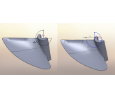
#2 Screen Shot of 50% radius section view
by tsalpha

Download Files
#3 7512-A Revision 2
by tsalpha

Download Files
#4 7512-B Revision 2
by tsalpha

Download Files
#5 7512-C Revision 2
by tsalpha

Download Files
#6 Original Prop Tapered surface
by tsalpha

Download Files
#10 7512-AV V-Cup Question
by tsalpha

Download Files
#14 Data Sheet for 7512 Props
by tsalpha

Download Files
Discussion
That should be it for the 7512 set of props. Please close this contest. I will try to have the 7016 series finished by Monday. Thanks.

All good and correct. As for the V-cut - 2nd drawing - starts from the edge of HUB not from the center of the prop.
Finish up and 2 Gold medals for you and you can concentrate on the super charger .
Finish up and 2 Gold medals for you and you can concentrate on the super charger .

Please check revision 4 for 7512-A, 7512-B, 7512-C, I think we may have it. I also have a question in regards to the V-Cup dimension. Please see design 10. After the V-Cup is taken care of I will have everything I need to finish all of the 7016 props.
Still need to know if tapered surface along original trailing edge remains on new prop. Please check current revision.
Yes now you are on the right track cupping from 40% - 90%, trailing edge original thickness with thickness increasing towards the hub.
I was unclear in regards to cupping starting at 40% and ending at 90%. My current model has the cupping along the entire trailing edge, this could be modified with additional information. Also unclear about trailing edge thickness, original prop has blade becoming thicker towards the hub at the trailing edge. Without any info, I made my trailing edge the same thickness as the leading edge.
could not really see that the cupping starts at 40% of radius and end at 90% of radius. Can you show me a cross section view at 50% radius so I can see the curvature at 30 degree and the drop in mm.
Design submitted for first modification, rest to follow, if these are correct.
Revised H1 H2 Angle uploaded, disregard previous file.
that drawing is not to scale - diameter is 75 mm - 2/3 diameter is 50 mm - the radius should be 12.5 mm. Use this radius intersects with the leading & trailing edge to measure the angle..
In your picture H1 H2 angle, 3/4 diameter seems correct, but shouldn't 2/3 diameter be 1/2?
Similar Contests on Cad Crowd
Modification to Props 2nd Project
to incorporate some radius requirements at the trailing edge of props, to take measurement of height and angle before and after incorporation. To supply 6 drawings and measurements in iges format.
2D drawings in Solidworks
Follow the Procedure to produce 2D drawings (See PowerPoint for method). Really repetitive work. There are 4 Solidworks files in attachment to make a test. We will have hundreds of those to do.
Timing pulley - SolidWorks Designer
very simple timing pulley.
First to summit the complete work will get the prize.
SolidWorks Simple Box with 2 Cords - Freelance 3D Designer Contest
Keep the dimensions of the box exactly as they are in the 2D version (they are in imperial but can be changed to metric in the solidworks file) I'm looking for a clean 3D Solidworks file of the exterior with the 2 cords that can pull out almost to look like an assembly drawing in Solidworks. I'm not looking to get detailed on what the product is or how it will work, but the top port is a Micro USB, and the bottom port is a Lightning USB. The notches on both are for fingernails and a cord will pull out. There is a very small power button on the bottom and 4 LED lights on the back side that I will update soon. I'm looking for conceptual nice looking design to use for sale of the product.
PDF to SolidWorks
Convert PDF to Solid Works 14
tsalpha
Designer