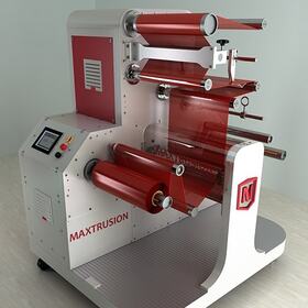
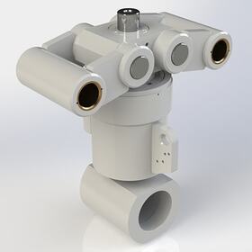
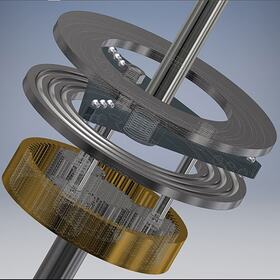
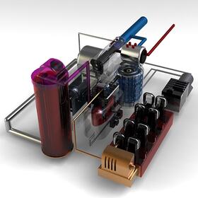


From the initial discussion and concept phase to the production of your product, the 3D modeling of machine parts can help you optimize your design, bringing speed, precision, and enhanced visualization to each stage of the manufacturing process. This adds additional benefits, such as reduced lead times and manufacturing costs.
3D modeling using computer-aided design (CAD) allows engineers and CAD services to build realistic computer models of the product. From a simple one-piece component to a multifaceted system such as a Formula 1 racing car, using 3D CAD modeling enables the product to be brought to life in a virtual environment. From here, many "what-if" scenarios can be performed. You can implement design changes on the fly, and you can complete design enhancements in real time at a vastly reduced cost compared to building multiple physical prototypes.
Solid models are created by developing a mathematical representation of an object in three dimensions. This representation is a virtual physical body that defines the volume of the object it represents. Typically, the designer determines the process by which a component is to be manufactured and applies the correct methods using the CAD software being utilized.
While there are subtle differences between the different CAD packages on the market, the procedure is similar for each, and involves the designer creating primary, secondary, and tertiary features of the model.
Primary features of a machine component are the main bodies of that component. A CAD modeler will usually create 3D primary components using the following methods:
In addition to creating primary features, a designer can also remove parts of these features using the CAD software. For example, a revolved shape (say, a cylinder) can be utilized to create a channel in a primary body (such as would be done in a typical CNC manufacturing process). Changing the shape and dimensions of a primary body will necessitate the recalculation of the load or stress factors on a component to see if it meets with the required safety factors; state-of-the-art software can handle this task automatically.
Secondary features of a machine component consist of elements that typically assist with the assembly of components to one another. These can include holes, threads, spigots, etc., and are generally available to the designer through menus in the software. The modification of these features may have some bearing on the design of the component but would not be considered as critical during analysis (they are, for the most part, removed during finite element analysis).
Tertiary features consist of the components that have no real influence on the design; the modification of said components is considered to be trivial from a design perspective. An example is the removal of sharp corners (chamfers) or the engraving of a part number on the component surface.
If the manufacturing process is understood for a particular component, there are other tools to assist the designer in the definition of that part. Sheet metal or forming software add-ons allow the designer to create manufacturing-specific processes such as bending, punching, and notching, along with the ability to "flatten" or develop the component. With processes such as forming or injection molding design, the ability exists to create forming or press tools by simply using Boolean functions such as "subtract" to create an accurate representation of the designed part in its inverse state.
If the component is to be manufactured using a 3D-printing process (such as laser sintering), it's considered an industry best practice to create a latticework on structural members to reduce mass. This is an intricate process that is difficult to accomplish by normal methods. But with a recent innovation known as generative design, the designer specifies parameters such as material, loads, constraints, and design space; the software then generates a 3D geometric solution.
For the more aesthetic elements of a machine component such as molded covers, rubber fixtures, handles, or the parts of the assembly that consist of a more free-form or organic shape, a methodology called surface modeling is used. Surface modeling represents components with a technique called wireframe modeling.
Wireframe modeling gives the designer more freedom initially regarding shape definition; however, the ability to modify the basic profiles is more complicated later on in the design process. Once a wireframe is complete, the model can be closed to form a solid that will become an integral part of the machine component or assembly. It is not uncommon for both solid and surface modeling to be utilized in a 3D model.
Assembly modeling allows for all the individual components to be assembled as one. The 3D modeling of machine parts will, for the most part, form only the parts of the assembly. It is often up to the designer to determine what methodology will be used for creating the assembly drawings—either a top-down or bottom-up design approach:
Applying material properties to the modeled component allows for the design simulation of the 3D model within the modeling software and the ability to see if the design conforms to currently valid standards (such as ANSI, DIN, ISO, AGMA, etc.). To ensure the design meets its product-life parameters, the assembly interference checks can be performed to ensure that all components fit.
When you need design services for your machine parts, let Cad Crowd put you in touch with qualified 3D modeling firms.
The machine design process is iterative. From concept review and preliminary design review to critical design review and even up to full production, there is only one constant—change.
Utilizing the advantages of 3D modeling and design can shorten the process of the prototyping design service.
Even today, the keystone of a design is the manufacturing data pack, which consists of a 2D representation of the designed components, documentation, and assembly instructions. Utilizing the speed and simplicity of the latest modeling tools, it is possible to create a full parameterized and associative data pack. A 3D model that has well defined "mates" linking the faces, edges, or primary features will, by association, update its corresponding components automatically.
Similarly, the 2D drawings that are automatically generated from the corresponding 3D model along with the defined attributes such as material types, dimensional tolerances, geometric dimensioning and tolerancing (GD&T), surface finishing, notes, and special instructions are also updated. The design intent is therefore captured automatically without the need for user intervention, ensuring revision control is seamless.
It is common for manufacturing companies to make use of generic 3D models generated by the CAD designer, especially in the prototyping stage, to generate CNC code to assist with the setup and manufacturing of the component. Utilizing the correct 3D modeling software can also ensure associativity between changes in the model and the subsequent CNC-generated code or 3D printing files, alleviating possible revision mismatches.
As an additional benefit, photorealistic rendering of the 3D CAD design communicates the design intent to the end user or client much earlier in the design cycle.
Working with Cad Crowd means working with only the best freelance CAD designers and 3D machine design experts worldwide. Our global network of 3D engineers is experienced in a wide range of industries and software. We offer a variety of design services beyond CAD design. We've got the solutions you need, no matter the shape, size, or scope of your project.
We're able to work with you using a variety of CAD software. Our designers are top-tier experts in these state-of-the-art design tools. Contact us today for a free quote!
