The injection molding design process, much like all industrial design processes, deals primarily with the creation, look, and feel of a product.
Unlike engineering services, the overall industrial design process does not focus much on the product’s functionality, but instead on its appearance and the ease with which it can be manufactured.
Excellent injection mold designs can mass-produce products with minimal molds and very few defects.
Subpar injection mold designs result in weak, defective products that are often unusable to boot. That’s why top-notch injection molding design is imperative for new products. Great molds cut costs to a minimum and improve production quality to meet end-user expectations.
Mold Components
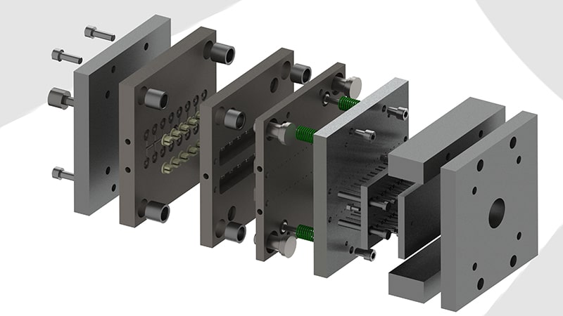
The Injection Mold
Injection molds are made for multiple uses, but their material makeup dictates just how many. Molds made from hardened steel provide long-lasting manufacturing potential for a higher price tag.
However, longevity isn’t the only factor at play in predicting price. The integral elements of the mold in question along with its overall complexity contribute quite a bit to the total cost of its initial creation.
Each of a mold’s major parts must be designed with care to ensure it works at all, let alone for years to come.
The Sprue
This piece serves as the entry point for molten material to pass through and enter the cavity within the mold.
Runners
These are individual channels connecting the sprue to the mold’s inner space.
Cavities and Cores
The cavity of a mold is its concave plate. The mold’s core is its convex one. Together, they form the inner space that shapes raw material into fully formed parts.
Inserts
Inserts are used when molds call for more complicated shapes or variations of the same part to be created. They are interchangeable subdivisions of cavities and cores.
Gates
Gates slow incoming molten material, regulating its flow as it enters parts of the mold.
Air Vents
These are often positioned around the mold’s parting line to ease the exit of air as material fills the mold.
The Ejector Mold
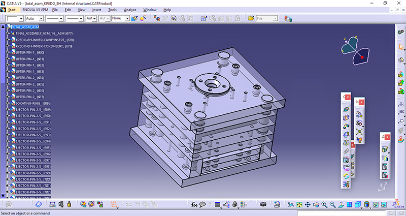
The ejector mold is typically tasked with safely removing the completed piece from once it is finished. This is usually accomplished with a single design technique…
Ejector Pins
Ejector pins provide a simple means of safely removing parts and pieces from their molds with a tap or press. Ideally, these are placed on runners rather than the piece itself as they are bound to leave ‘witness marks’ when removed, potentially marring the final part’s finish.
If any of the above parts of a mold are designed improperly, many annoying and often costly defects can show up on products at some point. Although a few of the mistakes that are made most often with injection molds are entirely due to the tools involved in the actual injection process, many more occur due to flaws in the injection mold design itself.
Knowing a few common issues that can arise may help you design significantly more effective and durable molds.
Below are 10 injection molding design mistakes you’d do best to avoid making.
10 Injection Molding Design Mistakes
Mistakes that Cause Color Defects
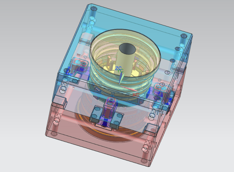
This first batch of potential injection molding design mistakes revolves around color issues caused by a variety of factors. With practical design principles in mind, each of these issues can easily be avoided before production ever begins.
1. Poor (or a Lack of) Venting
When proper venting is omitted or implemented poorly in an injection mold, discoloration can occur on finished parts.
The reason for this is the pooling and compressing of air in pockets, causing the air to ignite and burn the product as it is formed. For this reason, the defects caused by this mistake are often referred to as ‘air burns.’
3. Small Gates, Sprue, or Runners
If the gates of an injection mold are too small, a circular pattern can form on the parts nearest to them. This distortion of the final product is known as ‘gate blush’ or ‘halo’ and is often exacerbated by injection speeds that are too high.
4. Misuse of Gate Types
A variety of gate types exist, and the usage of gates that are incompatible with the material to be injected or the product’s design can cause a variety of issues to arise.
- Direct gates are the most straightforward gate design available. These are best suited for use in simple molds with only one cavity. They are known to leave a noticeable gate mark upon runner
removal, but work well for their intended purpose. - Fan gates minimize strain nearest the gate by providing a wider dispersion area. These are best suited to creating large parts relatively quickly.
- Straight top gates allow for products to be produced with no surface inconsistencies on their sides. Surface finishing on parts molded through the use of these gates can be cumbersome.
- Center diaphragm gates make molding concentric pieces particularly
easy, - Tab gates redirect shear stress from the injection molding process to a removable tab instead of the part in production itself. This type of gate helps drastically in the production of pieces with particularly slim
profiles, but makes finishing processes more tedious.
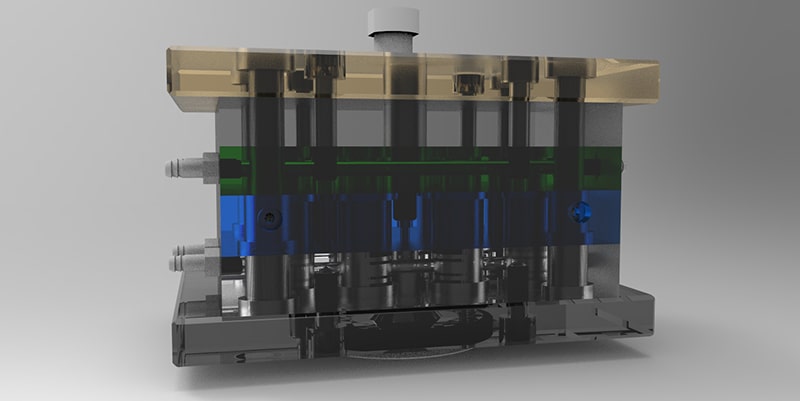
There are quite a few other types of gates to choose from in addition to the above, but utilizing the wrong ones for a specific task can bring about costly issues in production.
5. Leaving Out Mold Flow Analysis
Mold flow analysis of injection molds is a pivotal, though often overlooked, facet to consider for optimal results. This process is handled through the use of specialized software that predicts potential issues and pitfalls that can arise given a particular mold design and material choice.
Problems with mold flow usually result in defects such as “knit lines” (also known as weld or transfer lines). Such lines are a type of discoloration that occurs where two separate flow fronts meet.
The following mold design factors are contributors to this issue arising:
- Insufficiently large injection gates impeding the flow of material unevenly.
- Poor injection gate placement leading to uneven flow during the injection process.
- An excessive number of gates introducing multiple points of failure to the injection process.
Any of the above can result in “knit lines” on final products, but mold flow analysis prior to mold machining can keep these issues from cropping up at all in iteration and production.
Mistakes that Cause Structural Defects
All of the mistakes that follow tend to cause structural damage to injection molded pieces and products. Considered design can keep these potential issues to a minimum.
6. Improper Mold Parting
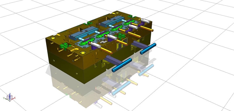
When the parting surfaces of a mold are incorrectly or carelessly designed, there is a chance for material to leak into the gaps between a mold’s halves during the injection process.
This effect is commonly referred to as ‘flash’ and can, in extreme cases, render produced pieces unusable. Designing parts with parting lines arranged on sharp, straight edges wherever possible can help to prevent this.
7. Improperly Placed Gates
When gates within an injection mold are placed in the wrong positions relative to incoming molten material, they can squeeze and restrict its flow, bringing about undesirable effects such as ‘jetting.’
Jetting is what happens when molten materials squirt through poorly chosen or poorly placed gates, failing to make contact with the walls of the mold and forming weld lines along the entire piece’s structure as the mold is filled.
These lines are deep-seated and compromise the structural integrity of the piece overall. Repositioning gates in your mold can keep this issue at bay.
8. Careless Cooling Channel Design
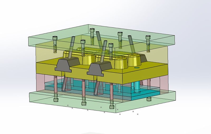
Even cooling of melted material injected into a mold is almost impossible to manage without properly designed cooling channels. These channels provide space for an applied coolant to circulate and quickly cool molded material before the mold is opened. Bad design in this area can result in defects such as ‘sinks’ which are noticeable depressions in the surface of a molded part. The following are important factors to remember when designing cooling channels:
- Thick walls increase the need for larger cooling channels to accommodate them.
- The mold’s interior space and the cooling channels should be kept as close to each other as is permissible.
- Air traps can form within dead ends in cooling channels, so these should always be avoided.
9. Excessively Thick Walls
Thick wall sections of a piece are much more prone to developing ‘voids.’ Voids are a lot like inverted sinks. If the molded part’s surface cools faster at a point than the rest of the material, then some of the material will stick to it as it shrinks and cools. Avoiding this issue is, in many cases, as easy as designing parts with less thick sections.
Bonus Mistake
10. Not Iterating Your Design Process
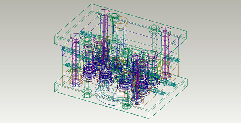
Working with the first design you’ve completed can yield decidedly unimpressive results more often than not. Ideal designs are often discovered in the process of fleshing out “great” designs through iterative testing.
Overlooked areas of surprising importance can jump out at you when your mold is put to the test in mock production scenarios. Prototypes serve as the staple of this vital process.
Prototypes produce performance results you can improve upon over time. Each subsequent prototype patches up the failings of the last, leaving the product’s design in a much better position to accommodate the strict rigors of an industrial production environment.
Tips for Great Injection Molding Design
With a good grasp of the many common mistakes you can make in designing injection molds, you should be able to create some great ones. Here are a few helpful tips to keep you on the right track with your next mold design:
Rethink Gate Removal
Consider how easily your mold’s produced parts will detach from the gate or gates once they’ve finished forming. Inconvenient or awkward placement of gates can potentially increase manufacturing costs down the line if products require extensive finishing after molding.
Improve Your Wall Design
Great wall design in injection molds mostly revolves around thickness. This principle applies most noticeably to the relative thickness of walls in the context of other walls on the same part. Too large of a discrepancy between wall thicknesses typically leads to complications and defects.
Pick Mold and Part Materials Carefully
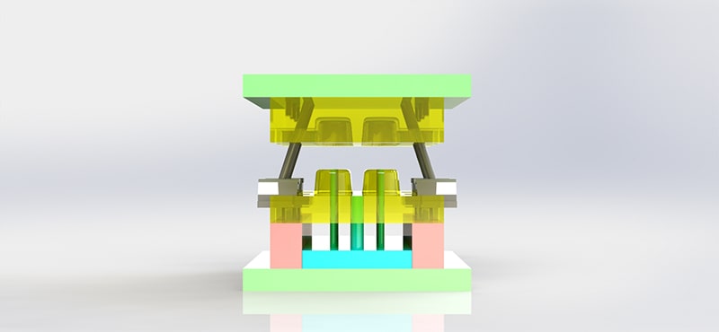
Mold Materials
High volume injection molds are almost exclusively made from tool steel. Tool steel comes in a variety of grades, varying on the Rockwell hardness scale and in terms of surface finishing.
- P-20 tool steel is a common choice and best used with non-abrasive plastics. It is pre-hardened to around 32 on the Rockwell scale and can be polished to SPI B-2.
- S-7 steel is a harder option, yielding the potential for hardening of up to 56 RC and high-luster polishing.
- Stainless steel and H-13 steel make pristine polishing possible and can be hardened to 52 RC. These options are great for medical products, lenses, and PVC.
- Aluminum is a great option for crafting inexpensive prototype molds. It boasts of quite high thermal conductivity in most of its variations.
Part Materials
A wide assortment of plastics provides plenty of choice for molding purposes, but some are much better suited to certain molds and materials than others.
- ABS thermoplastic is excellent for high-impact applications. As an amorphous material,
its melting point is flexible and slight modifications can further improve its toughness. - Polypropylene is the second most common commodity plastic in use today and works well for packaging purposes.
- PVC provides excellent hardness and insulation relative to other polymers. It ranks third in the world of polymer production, serving purposes as widespread as tubing, signage, inflatables, and canvas thanks to the versatility of its flexible and rigid forms.
Designing for Different Molding Processes
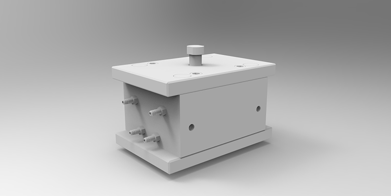
Injection molding design must always account for the process the mold is intended to be used with as material and form needs can vary greatly between them.
Multi-Material Molding
This molding process involves the use of multiple materials on a single part simultaneously. There are three variations worth considering:
Multi-Component
This form of multi-material molding produces sandwiched layers of material by injecting both into a mold at once. For optimal results, gates must be placed quite carefully in molds meant for use with this process.
Multi-Shot
Multi-shot molding is similar to multi-component molding in that sandwiched layers are produced through the process. However, this form of multi-material molding injects materials sequentially instead of simultaneously. Rotary platen and movable core options provide further variations on this process.
Over-Molding
This technique layers material over a single core structure. Over-molding typically requires the use of a separate mold for each material and produces parts that are fundamentally different from other multi-material molding processes as parts have usually cooled before having new layers applied.
Many other factors ought to be carefully handled at the injection molding design stage of product production to guarantee great results.
Cad Crowd Has Freelance Injection Molding Experts
Cad Crowd provides you with a wide assortment of pre-vetted professionals in CAD injection molding and casting services to choose from. Get in touch for a free quote today.
If you are interested in receiving multiple injection molding and casting design concepts, you can do so by launching a design contest. Find out how it works!
