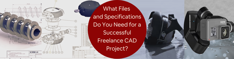
The project’s outcome can be determined at the briefing stage. Its success is not on the designer’s skills but on how clear the starting information is. When the designer receives defined deliverables, complete and clear files and specifications, they can produce better outputs with fewer revisions.
Vague briefs with missing information could lead to ambiguity and guesswork. The cost of back-and-forth clarification and rework can be high. This guide covers the necessary files and specifications needed for a successful CAD project. Once ready to start your project, CAD Crowd can connect you to vetted CAD designers who can help with project success.
🚀 Table of contents
Your design intent and project brief
A clear project description
To start, a clear project description is one of the most important aspects of a CAD project. It indicates what it is about and explains its purpose. It provides designers with context and background of the project, making them informed of the things to consider. With a clear briefing and a clear description of the context, designers can make the right technical decisions and anticipate the project flow. This reduces the need to guess the design intent, which could lead to misunderstandings and revisions.
A clear request means a clear deliverable. The key to success is allowing the designers to understand key information about the materials, manufacturing processes, and deliverable outcomes to make sure they are choosing the right approach.
RELATED: Tips for Strategic Product Briefs that Prevent Costly Rework with Top Design Firms
Intended use of the final deliverable
One of the most overlooked yet important details in a project brief is how the final output will be used. Knowing this lets the designers understand how the model has to be built, what level of detail is needed, and which file formats it has to be exported. Each usage requires design decisions. This means that every model has its intended and proper workflows to ensure efficiency.
When the end use is not clear, the designers may produce a model that could fail in real-world environments. There could be problems in manufacturing or production. Or a supposedly marketing use couldn’t be done because of file formats.
Target industry or application
A strong brief includes a clear industry or application it belongs to. This means that the field it serves has to be identified. This is because CAD standards are not universal. It changes depending on the field and end use. One application is how architectural drawings follow different rules and conventions from mechanical drawings.
Oil and gas projects use ANSI/ISA for their P&ID diagrams. Structural steel design works follow AISC standards. Each discipline and industry has its own specific symbols, styling, and tolerances they follow. When the industry is not clearly stated, the designers may opt to use their default standards, which may lead to a mismatch in project requirements.
RELATED: Product Development Considerations that Can Make or Break New Product Ideas Before Launch
Number of design options or variants required
Often, the clients forget during the project brief how many design options they prefer. It is important to define the number of options required as it could impact the project timeline and cost. A single-direction project is a more straightforward approach. The designers would just develop one concept and improve it thereafter.
While a multi-variant project would require the designer to create several options, the client can choose one for further development. Considering several options could mean spending more time creating different designs instead of focusing on just one. That’s why mentioning it beforehand would properly set expectations.
Quality standards and certification requirements
Some CAD projects involve more than just producing an accurate set of drawings. There are regulated industries that follow specific quality standards, certification, and documentation compliance. This affects how the work is reviewed and executed.
The requirements are more than just knowing the final CAD file. It also determines the naming convention, tracking system, documentation, and approval workflow. That is why it is critical to include any regulatory or certification requirements in the project brief. Failure to do so would lead to rework and incur additional costs.
RELATED: How the Engineering Design Process Helps You Craft New Products for Consumer Goods Firms
Reference geometry and dimensional data
Dimensioned sketches and engineering drawings
One of the most useful references in general is a dimensioned sketch or an engineering drawing. It does not have to look polished or professionally drafted. It could be a rough sketch, but it has clear shapes, size, relationship, and dimensions. A simple sketch with annotations can help designers understand the model.
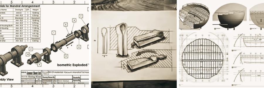
Missing dimensional information can cause delays and revisions. Designers would have to assume or ask questions just to make up for the missing data. This back-and-forth process can be avoided if only the reference data were complete and clear.
PDF or scanned drawings (existing documentation)
There are projects based on existing designs or older sets of drawings. For these kinds of projects, it is very helpful to provide reference drawings or documentation. For instance, a renovation project has to be done. The existing drawings are helpful in determining the overall placement of structural,architectural, and MEFP elements. It helps designers understand the design intent and imagine how the renovation will be done. It gives them an accurate foundation of information.
Providing multiple references helps designers cross-check information and dimensions. This way, it helps in reducing inconsistencies and assumptions. A complete set of plan views, elevations, sections, and detail drawings is appreciated to create a more accurate deliverable.
Physical measurements and callout sheets
A physical callout sheet consists of photos or sketches of objects with clear dimensions and feature locations. The measurements include its overall length, height, and the spacing or thickness of its components. A callout sheet is more reliable when it’s organized and complete, helping designers develop an accurate model.
RELATED: A Guide to Concept Design with Product Design & Engineering Companies
The accuracy of measurements relies on the tools used. It could be taken with tape measures or vernier calipers. In the architectural and structural fields, laser distance and measuring tape are used.
Reference images and photographs
One of the most important references in CAD projects is images and photographs. Dimensions do not fully explain and interpret the design. To better communicate the model’s overall appearance, proportions, and physical attributes, reference images and photos are needed.
It is especially useful and applicable for product design and reverse engineering work. The photos provided should be clear enough and taken from multiple angles. These help designers avoid assumptions and focus more accurately on digitalizing it.

Existing CAD files (native or neutral)
Although not always available, if there’s an existing CAD file, even though it’s old or just a similar type, it is helpful to share it with the designers. The existing files help designers avoid starting from scratch. With these, they’d have a base model to work on and modify, saving them more time.
RELATED: How Can Accurate 3D CAD Modeling Benefit to the Design Process of Your Firm
Even when the files are old or outdated, they can still show the structure. Native CAD files such as SOLIDWORKS (.sldprt), Revit (.rvt), or AutoCAD (.dwg) formats are recommended to be provided, as they preserve parametric features. This makes them editable and easier to modify.
Technical specifications
Material specifications
One of the most critical files needed in a project is the material specifications. This documentation consists of important information such as how a part is designed, manufactured, and documented. Materials have unique attributes, leading to different manufacturing limitations and design requirements. The designer needs this information in order to make efficient and effective design decisions.
The material specification provided should contain enough information and description for it to be reliable. It is not enough to just say “plastic” or “stainless steel”. It has to be more detailed and specific since each material behaves differently in a real-world setting.
Manufacturing process
Another important piece of information is the manufacturing process. This technical detail helps in understanding the model to be built. Every manufacturing process differs in methods, limitations, and design rules. The designers need to know which one is set in order for them to make informed decisions.
RELATED: How Design for Manufacturability (DFM) Services Help with New Product Design at Your Startup
When the manufacturing process is not defined, the final design model may be difficult to build or expensive. This may result in a redesign, costing more time and money. Knowing the manufacturing process allows designers to anticipate potential issues, enabling them to address them early.
Tolerances and fit requirements
Tolerances define the accuracy of a manufactured part of the model. It states how much variation is allowed from the exact dimensions in the design model. It varies depending on how critical the part is. This is important since tolerances impact how the parts fit together.
If the tolerance value is not yet defined, another solution is to describe how the part functions. An experienced designer can analyze and recommend an appropriate fit and tolerances suited for the manufacturing method. A clear and defined tolerance and fit requirements reduce errors and costly rework.
Surface finish requirements
A surface finish refers to the overall texture attributes of a part’s surface. It defines how smooth and rough the surface is. Knowing this helps designers understand how it looks and functions. While sometimes overlooked, this detail is important in manufacturing quality and product performance.
RELATED: How 3D Modeling is Beneficial in Product Manufacturing & New Product Development Services
Surface finish impacts the level of precision it requires. It ensures that the final product matches the intended look and durability. A clear definition of surface finish requirements enables designers to align the model with client expectations, ensuring design consistency and functional accuracy.
Thread and fastener specifications
In manufacturing, one of the most encountered problems is a mismatch in threaded holes and fasteners. This could be caused by incorrect specifications or a lack of information provided. It is important that the designer receives complete specifications to ensure accuracy in assembly. The specifications should also include the fit tolerances, size, and compatibility of the threaded feature. The thread standard, such as Metric, Unified, or BSPT, should be clearly defined.
For bolts and other hardware like screws, specifications should include details such as proper clearance holes, tapped holes, and countersinks. Knowing fastener information lessens the problems it may face during the manufacturing process.
Assembly context and interface geometry
Most projects done in CAD are part of an assembly. It’s mostly parts that work with other components and not as a standalone project. Because of this, the designers need to understand the whole assembly context to know the relationship between the parts, their connections, and how much space is available around them. They have to accurately have an image of how the part interacts with its neighboring parts. This is called interface geometry.
RELATED: Top 5 Prototyping Mistakes to Avoid in Product Development (And How to Fix Them)
Knowing interface geometry helps designers to create accurate connections and clearances. It reduces possible misalignment during production. Interface geometry can be provided by sharing the CAD models of surrounding components.
Weight and dimensional envelope constraints
There are CAD projects that have strict weight requirements. These are called dimensional envelope and weight constraints. In these types of projects, every small change is critical due to strict constraints. This is mostly applied in aerospace field expert.
The designers should know of the constraints that are set at the start of the project. They have to be informed and aware of the limitations in order to consider them in their design. It is critical to set required clearances and weight limitations for the designers to make efficient and smart decisions. It allows them to carefully analyze the best optimization approach to account for constraints.
Regulatory and standards compliance requirements
There are projects that follow specific industry codes and standards. The standards define how the drawings will be developed, annotated, documented, and reviewed. It is critical that these requirements are briefed before the start of the project. Doing so can help avoid the possibility of costly rework and delay.
RELATED: The Role of Cross-Functional Teams in Accelerating Product Design Innovation
Compliance requirements may change the project’s scope. This is because there are standards that would require a drawing or technical documentation. For example, a drawing may require a Professional Engineer review and stamping, or a certain model needs to be more detailed and validated to comply with the standards.
File format and deliverable requirements
CAD file format: native vs. neutral
One of the most important pieces of information during the project brief is specifying what file format is expected for the final deliverable. CAD files can either fall under native or neutral formats. Each serves a significant purpose. The right file format generally depends on file usage and application.
Native formats are parametric and editable original files produced by CAD software. It includes file formats such as .dwg (AutoCAD), .rvt (Revit), and .sldprt/.sldasm (SOLIDWORKS). These file types are suitable for editing and updating base models. Neutral formats are file types that are designed to be compatible with other CAD programs. Most of the time, these files are not editable. It includes file types such as stp (STEP), igs (IGES), and .sat (SAT).
2D drawing format: DWG, DXF, or PDF
The most common deliverables for 2D CAD are DWG, DXF, and PDF file. Each of these formats serves different purposes and depends on the requested output by the client. This is why it is important to set up an expected file format for the deliverables to ensure proper alignment.
RELATED: How to Quickly Cut Prototype Design Costs in 2026 for Product Design & Engineering Firms
When the output is for review, printing, and approval, a PDF is usually used. It is a fixed file format that can be viewed on almost all devices. DWG and DXF files are editable and can be useful, especially when the design is expected to be edited, revised, or updated. Most of the time, PDF is used as a final issue, so it can’t be edited or modified.
3D visualization and rendering formats
Visualization and 3D rendering deliverables may come with different file formats as specified in the project brief. Most of the static deliverables have file formats TIFF, PNG, and JPEG. TIFF and PNG are high-quality formats best for printing materials, while JPEG is of lesser quality and is best for online catalogs or websites.
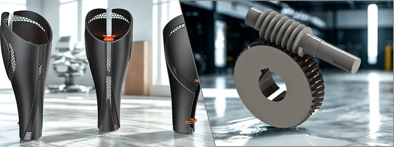
If the render is to be printed, it is important that the image size and resolution are specified. For instance, a large-format poster needs a resolution of more than 300 DPI. For interactive 3D content, file formats vary depending on the platform. GLB and GLTF are used for web-based 3D viewers, FBX and OBJ are for animation software and VR workflows. MP4 is used for video walkthroughs.
BIM model LOD and data requirements
BIM projects have a certain required Level of Development or LOD. It is important that it is clearly defined and specified during the project brief. LOD covers how detailed the BIM model needs to be, either visually or technically.
RELATED: The True Cost of Injection Molding vs. 3D Printing for Product Prototyping Services
A low LOD level is for concept or early-stage planning. High LOD is for coordination, fabrication, and construction. For instance, LOD 100 represents basic conceptual massing, and LOD 200 is for approximate geometry. In LOD 300, it contains even more accurate dimensions and details for construction coordination. It progresses along with how rich information is needed.
Drawing sheet size
In the project brief, it is important to specify the required sheet size for the CAD project. This is important because it affects the way the drawings are organized, printed, and reviewed. The sheet size could vary depending on the region and preferred format.
In the US, the most common engineering drawing sheet sizes are A (8.5×11), B (11×17), C (17×22), D (22×34), and E (34×44). While for international projects, ISO paper sizes such as A4-A0 are used. Some firms prefer customized layouts as well. It is important that this is discussed in order to keep workflows aligned.
Title block requirements
Title blocks contain important information in the project. It is best to specify in the project brief what information they prefer to show. It could include drawing title, drawing number, revision logs, scale, issued date, company, and project details. Most of the time, the company has already established a title block template. The designer can request access to it to keep drawings consistent.
RELATED: Why Phase 0 Is Crucial for New Product Development and Physical Product Design Firms
The title block simplifies document control. It helps in ensuring all drawings are tracked and stored in a way that keeps them secure. Providing a title block to the designers allows deliverables to be consistent with the internal standards, ready for printing.
Layer and file organization standards
For large CAD projects, proper version management and file organization are essential to keep them consistent and easier to handle. When the files are properly organized, coordination is smoother and seamless. Revisions can be done simply and help future designers or members to understand the background of the project.
Every industry follows a certain standard. For instance, in US architectural projects, the NCS or National CAD Standard layer naming convention is used. The UK, on the other hand, uses and follows BS 1192 or ISO 19650 standards. For Mechanical CAD projects, simple layer structures can be used.
It is important to clearly set standards and guidelines required at the start of the project to ensure it matches the internal system. It could include layer names, colors, line weights and styles, text styling, and file naming.
RELATED: How Custom Enclosure Design Companies Help House Your New Electronics and PCB Products
Revision and version control requirements
Most projects undergo multiple revision cycles before the final output is approved. It requires numerous back-and-forth of discussion and approval. To ensure that everything is documented and tracked, a clear version control process is important to avoid confusion. This is done so that the changes made are tracked throughout the project.
Most large construction projects have an established document control system. It often includes revision history tables, with approved signatures, issued dates, and changes made. This is done to ensure that future revisions can be done, or that the team that will handle it next can easily understand the history of the project.
File naming conventions
One of the most overlooked details, but is actually impactful, is having a clear and consistent naming convention. It is easy to name a project just based on its name and description. However, when there are a lot of versions and revisions, it would be hard to track and trace. A proper naming system allows seamless and simple tracking, helping designers be organized in their work.
It could be put like this. A file name like “New_Final_Finalfinal_USE THIS” is confusing, unlike a structured name like “US Project 01_RevB_20260615”. The latter is easier to understand and track as it immediately shows important details of the drawing version.
RELATED: Advice for CAD Translation and Drawing Services for Your Company’s CAD Files
What to prepare before you post your project
A complete file checklist before you post
Before putting up a freelancing job listing on Cad Crowd hiring platform, it helps to prepare a checklist and organize it. This is useful for a clear project brief. The designer would be able to follow through with what the project needs or requires them to do. This reduces confusion and assumptions that could result in delay.
The checklist could include, but not be limited to:
| 1. Dimensioned sketches, photos, reference drawings and models |
| 2. Material specifications/Technical specifications |
| 3. Manufacturing processes/Production processes |
| 4. Required deliverable formats |
| 5. Naming conventions |
| 6. Regulatory standards if required |
| 7. Timeline expectation |
| 8. NDA |
| 9. Point of contact/correspondence |
| 10. Payment terms and conditions |
How Cad Crowd uses your files to match you with the right designer
Cad Crowd is known for its tailored matching process. It uses the information included in the project brief, reference files, and technical requirements to connect businesses to the right designer or freelancer. This helps clients and businesses save time in filtering candidates who are fitted for the required deliverables.
The accuracy of the matching process depends on how detailed and complete the project brief is. This is why it is important to ensure that all information is provided, including software process, standards, and a timeline. Clear briefs mean clear deliverables. Cad Crowd can help in connecting with the right freelancers in a more efficient way.
Common mistakes that derail CAD projects
Several projects experience delays, extra costs, and revisions because of preventable mistakes during a project brief. Communication is one of them. It is important that the designer and the client have clearly communicated to each other the scope and deliverables of the project. Another is a lack of references, such as drawings and photos. To better align with the expected geometry, it is best to provide technical references.
RELATED: Learn how to Write the Best 3D Rendering Brief
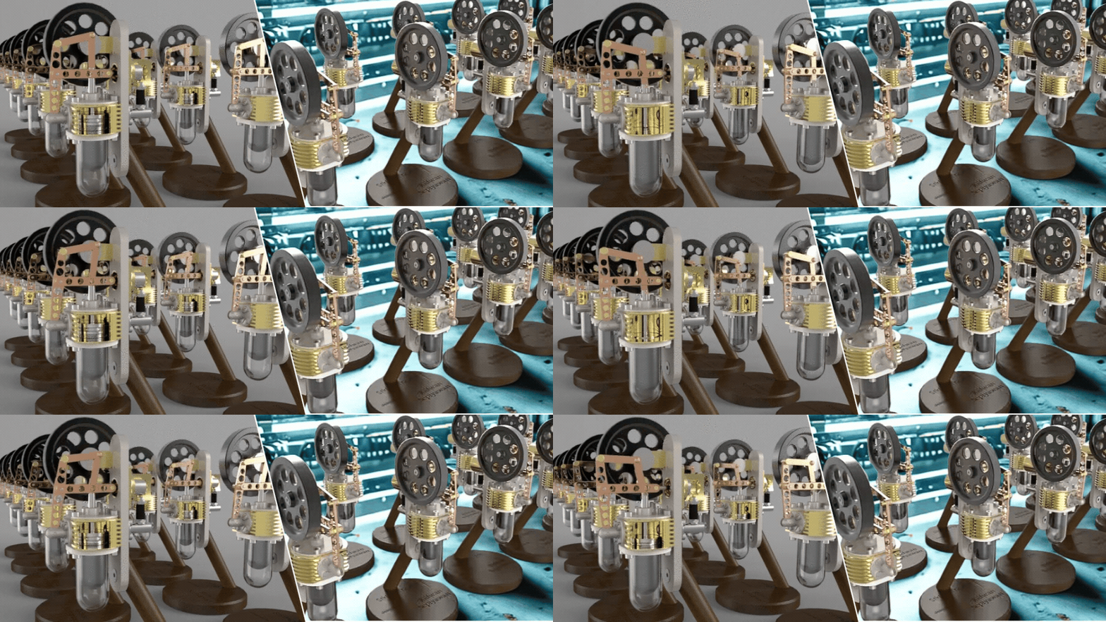
Another avoidable mistake is undefined file format requirements and drawing standards. Specifying this firsthand can help in reducing time-consuming rework or file conversions. There are still other avoidable mistakes that are overlooked, but a clear checklist can resolve them.
Conclusion
The success of a CAD project depends on how well-prepared and clear the project brief is. When all information is provided and defined, designers can accurately deliver the tasks expected. The more complete the information is, the less misunderstanding and confusion there is. A structured brief also makes it easier to come up with an accurate quotation and realistic timelines. Cad Crowd can help in efficiently connecting businesses with screened designers, tailored to their project needs.
How Cad Crowd can help
A successful CAD project starts with a clear project brief and complete technical documentation. Cad Crowd connects businesses with experienced CAD designers and engineering professionals who can turn your project requirements into accurate, high-quality deliverables. Whether you need 2D drafting, 3D CAD modeling, engineering drawings, BIM models, or product design support, our vetted experts can help streamline the design process, minimize revisions, and deliver reliable results. Contact Cad Crowd today for a free quote.