Convert Existing Survey to Modern As-Built CAD Drawings – Residential
in
Architectural Design
held by
dennish2
Last seen:
TIME REMAINING: 12 days, 23 hours
-
Open
-
Choosing Finalist
-
Ended
Description:
This project involves converting an existing professional measured survey into modern, code-compliant as-built CAD floor plans for a residential building originally built in 1892 as the personal estate house of Michael John Curts, a master builder, later converted and permitted as a rooming house in 1953 (now apartment-house use), prepared as two linked drawing sets. The first set should depict the 1953 permitted footprint (rooming house). The second set should depict current conditions, layering in everything added since: the west side addition (including new footings, a new connection to the city sewer, and a revised roofline), and the fire escape stairways and exits. You'll be working from a signed 2010 appraisal report containing accurate room dimensions and a floor sketch for the entire occupied space, along with current photos of key areas to confirm layout. No site visit or field measurement is required, since the measurements are already verified and accurate, and nothing has changed since 2010. Drawings should include standard modern drafting details: room dimensions, fixture placement, a door/window schedule, and wall types, with each element that differs between the two sets clearly distinguished, for example through shading, hatching, or a legend showing "1953 permitted" versus "later addition." The building's basement is unfinished (concrete block and dirt floor, no ceiling or drywall) and is explicitly excluded from both sets. Deliverables should be provided as a scaled PDF at 1/4" = 1'-0" (not a raster export), plus an editable DWG/DXF version, with rooms labeled by use and each title block referencing its corresponding permit date: 1953 for the original set, current for the addition/fire escape set.
Wants:
Entries will be judged mainly on accuracy: how closely the drawings match the source dimensions, photos, and historical permit records, including handwritten notes and shotform annotations on the old inspection and permit documents. Entrants should demonstrate they can correctly read and interpret this older material, not just the clean 2010 appraisal. Clear visual distinction between the 1953 permitted footprint and later additions matters, as does staying within the stated scope and following the requested format.
Don't Wants:
I don't want stylized or overly designed presentation drawings, generic template floor plans that don't match the actual dimensions provided, guessed or estimated measurements where the source material is unclear (ask instead), any inclusion or estimation of the unfinished basement, or drawings that blend the 1953 footprint and later additions together without a clear visual distinction between the two.
File Size Limit:
25 MB +
Company Logo:
Yes
Software:
- 2D AutoCAD
 Payment Pending
Entries
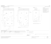
#2 As-Built CAD Drawings
by mechanical_3d
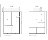
#1 The Curts House — Preliminary 1953 and Current-Condition CAD Documentation
by Eduardoeu
Discussion
WORKING

Hi,
Thank you for the detailed project brief. I understand the scope and the importance of accurately interpreting the 2010 measured survey, historical 1953 permit/inspection documents, handwritten notes, annotations, and current photographs.
I can prepare the two linked 2D AutoCAD drawing sets as requested:
Set 1 – 1953 Permitted Condition: The rooming-house footprint and layout corresponding to the 1953 permit.
Set 2 – Current Condition: The 1953 footprint with all subsequent additions clearly identified, including the west-side addition, new footings, sewer connection, revised roofline, fire escapes, and exits.
The unfinished basement will be excluded from both sets.
Drawings will include room/use labels, accurate dimensions, doors/windows, fixtures, wall types, schedules, legends, and appropriate drafting annotations.
Differences between the two conditions will be clearly distinguished using hatching/shading and a clear “1953 Permitted” / “Later Addition” legend.
Title blocks will reference the appropriate 1953 permit date or Current condition.
Deliverables will include a scaled 1/4" = 1'-0" PDF and an editable DWG/DXF file, while keeping the final files within the stated size limit.
I will not guess or estimate unclear dimensions or conditions. If any information in the historical documents conflicts with the appraisal, photographs, or annotations, I will flag it for clarification before incorporating it into the drawings.
My focus will be on producing accurate, permit-oriented as-built CAD drawings rather than a stylized presentation plan.
Please provide the 2010 appraisal, historical permit/inspection documents, current photographs, and any available reference files so I can review the source material and confirm the drawing scope before proceeding
Sudhir Tank
Thank you for the detailed project brief. I understand the scope and the importance of accurately interpreting the 2010 measured survey, historical 1953 permit/inspection documents, handwritten notes, annotations, and current photographs.
I can prepare the two linked 2D AutoCAD drawing sets as requested:
Set 1 – 1953 Permitted Condition: The rooming-house footprint and layout corresponding to the 1953 permit.
Set 2 – Current Condition: The 1953 footprint with all subsequent additions clearly identified, including the west-side addition, new footings, sewer connection, revised roofline, fire escapes, and exits.
The unfinished basement will be excluded from both sets.
Drawings will include room/use labels, accurate dimensions, doors/windows, fixtures, wall types, schedules, legends, and appropriate drafting annotations.
Differences between the two conditions will be clearly distinguished using hatching/shading and a clear “1953 Permitted” / “Later Addition” legend.
Title blocks will reference the appropriate 1953 permit date or Current condition.
Deliverables will include a scaled 1/4" = 1'-0" PDF and an editable DWG/DXF file, while keeping the final files within the stated size limit.
I will not guess or estimate unclear dimensions or conditions. If any information in the historical documents conflicts with the appraisal, photographs, or annotations, I will flag it for clarification before incorporating it into the drawings.
My focus will be on producing accurate, permit-oriented as-built CAD drawings rather than a stylized presentation plan.
Please provide the 2010 appraisal, historical permit/inspection documents, current photographs, and any available reference files so I can review the source material and confirm the drawing scope before proceeding
Sudhir Tank

I deliver precise, tailored solutions that bring guaranteed and efficient results, backed by a seamless, transparent, and reliable process.

Dear client ,
Please update contest to private(Blind) and pre paid!
Thanks
Please update contest to private(Blind) and pre paid!
Thanks

I am an elite Architect with 10+ years of experience in UAE ( DUBAI ) ,PAKISTAN,INDIA , USA, specializing in ultra-modern, high-end Luxury Residential , Commercial ,Industrial and Hospitality design. We are the team of young and Qualified Architects, Autocad Operators, Structural Engineer, MEP engineers and Interior Designers, Our work bridges the gap between jaw-dropping high-end aesthetics and flawless engineering precision. We don't just draft houses; We design immersive luxury lifestyles defined by sleek geometric lines, cantilevered structures, and seamless indoor-outdoor living.
SOFTWARES WE ARE USING:
1. AUTOCAD
2. REVIT
3. SKETCHUP.
4. LUMION
5. AI TOOLS FOR FAST AND PHOTOREALISTIC RENDERINGS.
"Give us a chance to bring your vision to life. We work through intensive your home and approve every detail before construction begins."
( YOU CAN REVIEW MY WORK IN MY PROFILE PORTFOLIO , I CAN ALSO SHARE THE PROJECT ACCORDING TO YOUR REQUIRMENTS IF YOU ARE INTRESTED.)
RECENTLY WE ARE WORKING ON 1 USA G+3 MULTIFAMILY & 1 HOUSING PROJECT FROM INDIA , I CAN SHARE YOU THE REFRENCE PDF FILE FOR REVIEW. THANKS .
SOFTWARES WE ARE USING:
1. AUTOCAD
2. REVIT
3. SKETCHUP.
4. LUMION
5. AI TOOLS FOR FAST AND PHOTOREALISTIC RENDERINGS.
"Give us a chance to bring your vision to life. We work through intensive your home and approve every detail before construction begins."
( YOU CAN REVIEW MY WORK IN MY PROFILE PORTFOLIO , I CAN ALSO SHARE THE PROJECT ACCORDING TO YOUR REQUIRMENTS IF YOU ARE INTRESTED.)
RECENTLY WE ARE WORKING ON 1 USA G+3 MULTIFAMILY & 1 HOUSING PROJECT FROM INDIA , I CAN SHARE YOU THE REFRENCE PDF FILE FOR REVIEW. THANKS .

Subject: 911 Bernard Avenue — Request for floor-by-floor measurements and existing plans
Hi Dennis,
We are preparing documented floor plans for 911 Bernard Avenue (“The Curts House”). The available permit records establish the addition and renovation history, but they do not provide enough measurements to draw complete, accurately scaled current-condition plans.
Could you please provide any existing measured drawings, particularly the signed 2010 appraisal and its floor-sketch pages? Please also identify any changes made since those drawings were prepared.
If measured plans are unavailable, the following information is needed. A separate annotated sketch for each floor is suitable. Please mark unknown or inaccessible dimensions as “not measured” rather than estimating them.
1. Ground/main floor
Please provide:
Complete exterior outline: overall width and depth; every exterior wall-segment length; dimensions and locations of bays, recesses, projections and changes in direction. Include angles or diagonal measurements where corners are not square.
West-side addition: length along the original building, outward projection, position relative to identifiable building corners, wall thicknesses, and the width and location of every connection into the original building.
Wall construction dimensions: finished exterior-wall thicknesses and the thickness of each distinct interior partition type.
Interior layout: location and length of every partition, wall return, recess and offset, including unit-separation walls.
Every room and closet: clear finished-face length and width; for irregular spaces, all perimeter lengths and sufficient offsets or diagonals to define their shape.
Foyer, vestibules and corridors: clear widths, lengths, constrictions, turns and junction locations.
Every door and open passage: opening width, height, corner-to-jamb offset and reveal depth; door-leaf width where different from the opening. Please identify the hinge side and swing direction.
Every window: opening width and height, corner-to-jamb offset, spacing between adjacent windows, sill and head heights above finished floor, and recess depth. For bay windows, include projection, side lengths and angles.
Main stair and other internal stairs: flight locations, clear widths, horizontal runs, tread counts and tread goings; landing lengths and widths; stairwell/opening dimensions; floor-to-floor rise, riser heights, landing elevations and headroom.
Fixed kitchens and bathrooms: cabinet-run lengths, counter depths, and the actual footprints and wall offsets of sinks, toilets, showers, tubs, enclosures and fixed appliances.
Other fixed elements: dimensions and locations of radiators, chimney breasts, columns, shafts, boxed services and utility cupboards.
Entrance connections: door thresholds and adjacent landing elevations, including any steps between interior floor level and exterior entrances.
Laundry, if on this floor: room dimensions, access-opening dimensions, and washer/dryer footprints and positions.
Please identify which units occupy this floor and which spaces are shared.
2. Second/upper floor
Please provide a separate measured plan; please do not assume it matches the ground floor.
Required measurements are:
Exterior outline: overall width and depth, every wall segment, bays, recesses and projections, including offsets relative to the floor below.
Any west-addition accommodation: its extent on this floor, wall thicknesses, and dimensions and locations of connections to the original building.
All walls and partitions: thicknesses, lengths, locations, returns and offsets, including unit boundaries.
Every room and closet: clear dimensions and complete geometry of irregular spaces.
Corridors and shared circulation: clear widths, lengths, constrictions and turning/junction dimensions.
Every door/open passage: opening width and height, corner-to-jamb offset, reveal depth and leaf width where different; identify swing and hinge side.
Every window: opening width and height, corner offsets, spacing, sill/head heights and recess depth; complete bay-window geometry where applicable.
Stairs and floor openings: flight widths and runs, tread counts/goings, landing dimensions, stairwell/void dimensions and their offsets to surrounding walls. Include connecting floor levels, riser heights and headroom.
Kitchens, bathrooms and fixed appliances: actual footprints, cabinet/counter dimensions and offsets from walls.
Radiators and other fixed obstructions: dimensions and locations of radiators, columns, chimney breasts, service shafts, cupboards and boxed services.
Balconies and exterior access: platform lengths and depths, door locations, clear passage widths, and rail/post projections affecting access.
Please identify the units and shared spaces on this floor, and which doors connect to exterior stairs or balconies.
3. Attic or additional occupied level, if applicable
Please first confirm whether an occupied level exists above the second floor.
If it does, please provide:
The same complete footprint, wall, room, corridor, opening, fixture and stair measurements listed for the second floor.
Knee-wall locations and heights.
Ceiling heights and the locations where ceiling slopes begin or change.
Horizontal offsets locating restricted-headroom boundaries.
Dormer internal widths, depths and positions relative to the floor outline.
Dimensions and locations of roof windows and other openings.
Stair-access and landing dimensions, floor-to-floor rise and headroom.
Dimensions of any exterior platform or exit connection serving this level.
Please distinguish occupied rooms from storage or inaccessible roof spaces.
4. Exterior stairs, porches and exit routes — identify every level served
For each separate exterior stair, porch, balcony, landing or ramp, please provide:
Location and offsets relative to identifiable building corners.
Platform/landing length, depth and elevation.
Clear stair width, horizontal run, tread count, tread going, riser heights and total vertical rise between landings.
Rail, handrail and post positions/projections that reduce clear width.
Width and location of each serving doorway, including its swing.
Clear widths and constrictions along the route to ground level.
For ramps, clear width, horizontal run, total rise and landing dimensions.
Please identify which structure is the present fire escape and whether any older stair has been replaced or removed.
Measurement notes and remaining confirmations
Please record the measurement date, units, measurement precision and who took the measurements. Distinguish clear finished-face measurements from exterior dimensions or structural dimensions. Use consistent reference corners so openings and partitions can be located without guesswork.
We also need confirmation of:
Actual floor names and the current unit count/numbering.
Door swings and window operation.
The floor containing the photographed laundry area.
Known additions, partition changes or stair alterations since 2010.
Basement floor plans and below-grade room measurements are excluded. If the laundry is in the basement, confirmation of that location is sufficient.
Please do not enter inaccessible areas, remove finishes or climb onto roofs to obtain measurements. Any unresolved items can be marked for a measured survey.
Thank you,
VINAY
Hi Dennis,
We are preparing documented floor plans for 911 Bernard Avenue (“The Curts House”). The available permit records establish the addition and renovation history, but they do not provide enough measurements to draw complete, accurately scaled current-condition plans.
Could you please provide any existing measured drawings, particularly the signed 2010 appraisal and its floor-sketch pages? Please also identify any changes made since those drawings were prepared.
If measured plans are unavailable, the following information is needed. A separate annotated sketch for each floor is suitable. Please mark unknown or inaccessible dimensions as “not measured” rather than estimating them.
1. Ground/main floor
Please provide:
Complete exterior outline: overall width and depth; every exterior wall-segment length; dimensions and locations of bays, recesses, projections and changes in direction. Include angles or diagonal measurements where corners are not square.
West-side addition: length along the original building, outward projection, position relative to identifiable building corners, wall thicknesses, and the width and location of every connection into the original building.
Wall construction dimensions: finished exterior-wall thicknesses and the thickness of each distinct interior partition type.
Interior layout: location and length of every partition, wall return, recess and offset, including unit-separation walls.
Every room and closet: clear finished-face length and width; for irregular spaces, all perimeter lengths and sufficient offsets or diagonals to define their shape.
Foyer, vestibules and corridors: clear widths, lengths, constrictions, turns and junction locations.
Every door and open passage: opening width, height, corner-to-jamb offset and reveal depth; door-leaf width where different from the opening. Please identify the hinge side and swing direction.
Every window: opening width and height, corner-to-jamb offset, spacing between adjacent windows, sill and head heights above finished floor, and recess depth. For bay windows, include projection, side lengths and angles.
Main stair and other internal stairs: flight locations, clear widths, horizontal runs, tread counts and tread goings; landing lengths and widths; stairwell/opening dimensions; floor-to-floor rise, riser heights, landing elevations and headroom.
Fixed kitchens and bathrooms: cabinet-run lengths, counter depths, and the actual footprints and wall offsets of sinks, toilets, showers, tubs, enclosures and fixed appliances.
Other fixed elements: dimensions and locations of radiators, chimney breasts, columns, shafts, boxed services and utility cupboards.
Entrance connections: door thresholds and adjacent landing elevations, including any steps between interior floor level and exterior entrances.
Laundry, if on this floor: room dimensions, access-opening dimensions, and washer/dryer footprints and positions.
Please identify which units occupy this floor and which spaces are shared.
2. Second/upper floor
Please provide a separate measured plan; please do not assume it matches the ground floor.
Required measurements are:
Exterior outline: overall width and depth, every wall segment, bays, recesses and projections, including offsets relative to the floor below.
Any west-addition accommodation: its extent on this floor, wall thicknesses, and dimensions and locations of connections to the original building.
All walls and partitions: thicknesses, lengths, locations, returns and offsets, including unit boundaries.
Every room and closet: clear dimensions and complete geometry of irregular spaces.
Corridors and shared circulation: clear widths, lengths, constrictions and turning/junction dimensions.
Every door/open passage: opening width and height, corner-to-jamb offset, reveal depth and leaf width where different; identify swing and hinge side.
Every window: opening width and height, corner offsets, spacing, sill/head heights and recess depth; complete bay-window geometry where applicable.
Stairs and floor openings: flight widths and runs, tread counts/goings, landing dimensions, stairwell/void dimensions and their offsets to surrounding walls. Include connecting floor levels, riser heights and headroom.
Kitchens, bathrooms and fixed appliances: actual footprints, cabinet/counter dimensions and offsets from walls.
Radiators and other fixed obstructions: dimensions and locations of radiators, columns, chimney breasts, service shafts, cupboards and boxed services.
Balconies and exterior access: platform lengths and depths, door locations, clear passage widths, and rail/post projections affecting access.
Please identify the units and shared spaces on this floor, and which doors connect to exterior stairs or balconies.
3. Attic or additional occupied level, if applicable
Please first confirm whether an occupied level exists above the second floor.
If it does, please provide:
The same complete footprint, wall, room, corridor, opening, fixture and stair measurements listed for the second floor.
Knee-wall locations and heights.
Ceiling heights and the locations where ceiling slopes begin or change.
Horizontal offsets locating restricted-headroom boundaries.
Dormer internal widths, depths and positions relative to the floor outline.
Dimensions and locations of roof windows and other openings.
Stair-access and landing dimensions, floor-to-floor rise and headroom.
Dimensions of any exterior platform or exit connection serving this level.
Please distinguish occupied rooms from storage or inaccessible roof spaces.
4. Exterior stairs, porches and exit routes — identify every level served
For each separate exterior stair, porch, balcony, landing or ramp, please provide:
Location and offsets relative to identifiable building corners.
Platform/landing length, depth and elevation.
Clear stair width, horizontal run, tread count, tread going, riser heights and total vertical rise between landings.
Rail, handrail and post positions/projections that reduce clear width.
Width and location of each serving doorway, including its swing.
Clear widths and constrictions along the route to ground level.
For ramps, clear width, horizontal run, total rise and landing dimensions.
Please identify which structure is the present fire escape and whether any older stair has been replaced or removed.
Measurement notes and remaining confirmations
Please record the measurement date, units, measurement precision and who took the measurements. Distinguish clear finished-face measurements from exterior dimensions or structural dimensions. Use consistent reference corners so openings and partitions can be located without guesswork.
We also need confirmation of:
Actual floor names and the current unit count/numbering.
Door swings and window operation.
The floor containing the photographed laundry area.
Known additions, partition changes or stair alterations since 2010.
Basement floor plans and below-grade room measurements are excluded. If the laundry is in the basement, confirmation of that location is sufficient.
Please do not enter inaccessible areas, remove finishes or climb onto roofs to obtain measurements. Any unresolved items can be marked for a measured survey.
Thank you,
VINAY

Hi, I’m very interested in this project and would be glad to assist.
I have strong experience in **2D AutoCAD drafting, dimensioned floor plans, existing-condition drawings, technical documentation, and accurately interpreting source documents and site information**.
I understand that this project requires reviewing the **2010 appraisal, historical 1953 permit/inspection records, handwritten annotations, and current property photos** to accurately identify the original permitted footprint and distinguish it from later additions.
At the moment, the attachments on the posting are not downloadable from my side, and the linked website is also inaccessible. Once the project begins, could you please provide the original **PDFs, scanned documents, and photos directly**? This will allow me to review the source material carefully and produce the drawings without making assumptions.
I can deliver **clean, accurate, properly scaled 2D AutoCAD drawings**, including the requested **PDF and editable DWG/DXF files**, with clear dimensions and professional drafting standards.
I’m ready to start as soon as the source documents are available. I look forward to working with you.
I have strong experience in **2D AutoCAD drafting, dimensioned floor plans, existing-condition drawings, technical documentation, and accurately interpreting source documents and site information**.
I understand that this project requires reviewing the **2010 appraisal, historical 1953 permit/inspection records, handwritten annotations, and current property photos** to accurately identify the original permitted footprint and distinguish it from later additions.
At the moment, the attachments on the posting are not downloadable from my side, and the linked website is also inaccessible. Once the project begins, could you please provide the original **PDFs, scanned documents, and photos directly**? This will allow me to review the source material carefully and produce the drawings without making assumptions.
I can deliver **clean, accurate, properly scaled 2D AutoCAD drawings**, including the requested **PDF and editable DWG/DXF files**, with clear dimensions and professional drafting standards.
I’m ready to start as soon as the source documents are available. I look forward to working with you.
Hello Sir/Ma’am,
I’m an Architectural & Interior Designer offering professional design and drafting services at a cost-effective budget without compromising on quality.
I can handle different types of projects, including:
• Architectural 2D plans, elevations & sections
• AutoCAD drafting & working drawings
• Revit BIM modeling
• SketchUp 3D modeling
• Interior & exterior design
• 3D visualization & renders
• Residential and commercial projects
I’m available for freelance, part-time, or project-based work. You can share your requirements with me, and I’ll provide a suitable solution within your budget.
I’m also happy to start with a small project so you can check my work quality first.
Please feel free to contact me if you have any upcoming work.
Thank you.
I’m an Architectural & Interior Designer offering professional design and drafting services at a cost-effective budget without compromising on quality.
I can handle different types of projects, including:
• Architectural 2D plans, elevations & sections
• AutoCAD drafting & working drawings
• Revit BIM modeling
• SketchUp 3D modeling
• Interior & exterior design
• 3D visualization & renders
• Residential and commercial projects
I’m available for freelance, part-time, or project-based work. You can share your requirements with me, and I’ll provide a suitable solution within your budget.
I’m also happy to start with a small project so you can check my work quality first.
Please feel free to contact me if you have any upcoming work.
Thank you.

Hi, I’m interested in this project. I have strong experience with 2D AutoCAD architectural drafting, dimensioned floor plans, technical documentation, and existing-condition drawings.
I noticed that the project relies on the 2010 appraisal, historical 1953 permit/inspection documents, handwritten annotations, and current photos. However, the attachments on the posting are not currently downloadable from my side, and the linked site is not accessible.
Could you please provide the source PDFs/photos directly once we begin, so I can review the original documentation and accurately distinguish the 1953 permitted footprint from the later additions without making assumptions?
I’m comfortable working in 2D AutoCAD and can provide the requested scaled PDF and editable DWG/DXF deliverables.
I noticed that the project relies on the 2010 appraisal, historical 1953 permit/inspection documents, handwritten annotations, and current photos. However, the attachments on the posting are not currently downloadable from my side, and the linked site is not accessible.
Could you please provide the source PDFs/photos directly once we begin, so I can review the original documentation and accurately distinguish the 1953 permitted footprint from the later additions without making assumptions?
I’m comfortable working in 2D AutoCAD and can provide the requested scaled PDF and editable DWG/DXF deliverables.



Hello,
I am an architect with strong experience in AutoCAD 2D and architectural technical documentation, including floor plans, dimensions, elevations, sections, details, door and window schedules, and construction drawings.
I am very interested in this project because it requires careful interpretation of existing documentation rather than creative redesign. I can work from the 2010 assessment, historical permit documents, sketches, handwritten notes, and current photographs to accurately develop the two drawing sets requested.
I understand the importance of keeping the 1953 licensed condition clearly separated from later additions and current conditions. I can organize the drawings with clear layers, hatches, annotations, legends, and title blocks to make these differences easy to identify.
I can provide the final drawings as a properly scaled vector PDF at 1/4" = 1'-0", along with editable DWG/DXF files. I will also follow the specified scope and will not include or estimate the unfinished basement.
My approach is accuracy first: when information is unclear or conflicting, I prefer to verify it rather than make assumptions.
I would be happy to review the provided documents and begin working on the drawings.
Best regards,
Kelly Pereira
Architect | Architectural Drafter
AutoCAD 2D
I am an architect with strong experience in AutoCAD 2D and architectural technical documentation, including floor plans, dimensions, elevations, sections, details, door and window schedules, and construction drawings.
I am very interested in this project because it requires careful interpretation of existing documentation rather than creative redesign. I can work from the 2010 assessment, historical permit documents, sketches, handwritten notes, and current photographs to accurately develop the two drawing sets requested.
I understand the importance of keeping the 1953 licensed condition clearly separated from later additions and current conditions. I can organize the drawings with clear layers, hatches, annotations, legends, and title blocks to make these differences easy to identify.
I can provide the final drawings as a properly scaled vector PDF at 1/4" = 1'-0", along with editable DWG/DXF files. I will also follow the specified scope and will not include or estimate the unfinished basement.
My approach is accuracy first: when information is unclear or conflicting, I prefer to verify it rather than make assumptions.
I would be happy to review the provided documents and begin working on the drawings.
Best regards,
Kelly Pereira
Architect | Architectural Drafter
AutoCAD 2D
Similar Contests on Cad Crowd
Chalet village
Design a chalet house village of 10 units. You can make 1 big house or 10 small houses, each unit is around 43sqm with 2.60m height.
Here some insipiration: https://pin.it/2cnBD2D
location: https://earth.google.com/web/@46.77736543,11.2431423,1133.130909a,729.65335647d,35y,116.17874862h,41.37996526t,360r
Basement buildout ~ 1,700 sqft
We finished remodeling our main living area and are now looking to finish our basement. As an accountant I keep going back to the same two ideas. My wife and I are excited to see some ideas and ultimately choose one to move forward. The goal is to have a fun place for our son and his friends to hang out or the family and friends to watch sports. We are looking for a bedroom, full bath (shower, sink, toilet, area for stackable washer/dryer, linen closet), comfortable tv viewing area that can accommodate 8 +/-, small kitchen area with fridge, sink, some cabinets and floating shelves. We would also like an area for workout equipment (8x10 is sufficient). The games we'd like it to accommodate are ping pong, pop a shot, air hockey, darts, and foosball. An added bonus would be a built in area for two large dog kennels (3' x 5' x 3'). We are on septic so the bathroom discharge would need to feed into a small pit with a grinder pump. As such, the closer the bathroom can be to the main line the better. Note that the bedroom would need to be in the area with the egress window. My first time using SketchUp so please bear with me. Please let me know if you have any questions.
Private family home by a lake.
We are in the planning stage for our family home which is by a beautiful lake. The firm which took on our project has created a design and plans. We are happy with the floorplan; however, the frontal elevation is just not working. The house currently looks like a strange hybrid of two separate houses and an office building.
While we do want to maximize the views of the lake which are from the front of the house (north facing), we were hoping to really have something creative and beautiful that honours the nature around the house. The firm who has designed the plans is great with many build aspects, but we feel there is some creative thinking lacking.
We would like to hopefully find some fresh perspective and ideas on how we can make this "weird office building double house" look like one unique home.
A quick note on the plans - we're renovating (and adding) to an existing duplex, and the builder designed the house with the possibility of one day separating it into two houses with minimal build costs. You will notice this from the plans.
Creative Exterior Concept Design - Vertical Building
I am looking for an elevation façade for my new laid-back luxury hotel. It’s around a 20-story structure building on a 4-story base floors. Each floor slab is around 12,000 square feet ( 100'-0" x 325'-034"). Line elevation drawings are required, along with one final 2D drawing with wall sections or a basic color-coded 3D image.
Other files:
1. Overhead view drone elevation
2. South east exterior
3. South west exterior
4. Right and left exterior
5. Zoom out exterior with 2D street map elements (optional for better viewing and presentation)
All set of dry run files from the previous designer are available upon serious interest and participation. Thank you!
Simms
Currb appeal transformation.
I have been looking for an exterior designer/decorator which is turning out to be bit of a challenge for what I need. Which is a curb appeal makeover and importantly a facelift to my small ranch.
It is a foreclosed ranch with outdated vinyl siding,cedar shakes siding in front, an unkempt yard with large ugly logs as borders for the garden and side yard. I would like to transform the house using beautifully coordinating siding, trim, lineals, stone veneer, plants, garden, architectural accents like mahogany corbels, deck color to match siding. I am not looking to make major structural changes that involves demolishing and rebuilding, but looking for the ultimate curb appeal without major construction for between $15-20,000
Design concept to include:
- beautiful dramatic but timeless coordinating vinyl siding, trims, windows and stone veneer accent.
- coordinating window trims/molding colors
-deck color to coordinate with siding
- Front Yard Landscape ideas - floral and hardscape ideas for borders around garden and side yard.
- House front wall accents mount mail box, lighting sconce flower pots
-Open to small architectural accents, but no demolishing and remodeling.
-overall front yard curb appeal
-Siding and foundation wall is ugly and dirty, Looking for someone to present design ideas and concepts to give the house and front yard a dramatic face-lit. I will take care of my contractors, just looking for the design creation. I have photos, is this something you can help with create online for a reasonable fee? I have a lot of pictures just adding one here.
Importantly if this something that can be done, I live in NJ so materials, siding, veneer etc should be available in the northeast.
naseerb