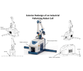
Exterior Redesign of an Industrial Palletizing Robot Cell Blind
in
Industrial Design Services
held by
pierreetiennegermain
Last seen:
Contest Ended, Winner(s) have been selected.
-
Open
-
Choosing Finalist
-
Ended
Description:
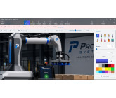
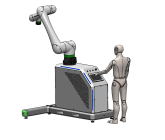
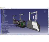
We manufacture robotic palletizing cells built around a Fanuc CRX collaborative robot arm mounted on a fixed cabinet/pedestal. You can see our current machines and product line at www.probotsystems.com/fr/palletiseur/. Attached are photos of the current unit, a CAD screenshot showing the existing footprint, and a couple of screenshots of the touchscreen app that runs on the machine, just for context on the overall product feel.The current exterior is purely functional and honestly looks like a metal box. We want a real industrial design pass on the shell: something that looks like a premium, next-generation robotics product while still being realistic to manufacture in bent/formed sheet metal, or laser-cut sheet metal. We're also open to other materials, just keep in mind this machine lives on a factory floor, so whatever you propose needs to hold up in an industrial environment. 3D-printed parts are acceptable for certain components too.
We're based in Canada, so we work with North American material sizes and imperial units (standard sheet stock sizes, gauge thicknesses, etc.). Keep that in mind if you're sizing panels. We also have access to a tube laser, so laser-cut tube/profile stock is fair game too, not just flat sheet.
This is not a blank slate though. The robot itself, the base, the controller, and the electrical panel stay roughly where they are functionally, but there's some flexibility, they can shift a bit or be stacked differently if it helps your design. The T-shaped base itself is also open for redesign, not just the shell around it, as long as it stays within the dimension ranges given below. What we need redesigned is the whole exterior look, done right, with the LEDs, the door, and the shipping clearances all working together instead of being an afterthought.
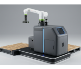
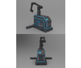
I attached a couple of AI-generated concept images we liked for the general mood (dark grey shell, glowing blue LED accent lines, laminated vinyl graphics). Feel free to look at them for the vibe, but don't treat them as a spec, we're open to your own direction as long as the requirements below are respected.
For the level of build quality and industrial design we're aiming for, look at companies like Trumpf, DATRON, DMG Mori, DN Solutions, and Markem-Imaje, they all make industrial/CNC equipment with genuinely great design, several are Red Dot Design Award winners. We've attached a few photo examples from these brands for reference.
Key Components & Dimensions
Electrical panel: approx. 20 x 16 x 8 in (508 x 406 x 203 mm) (length to be confirmed, could be up to 24 in / 610 mm)
Robot controller: 410 x 277 x 370 mm (16.1 x 10.9 x 14.6 in), with cable connectors on the right side, that side needs to stay accessible/have clearance
The current operator interface is not a built-in touchscreen, it's a Samsung Galaxy Tab Pro tablet mounted in a Fanuc teach pendant holder, with a physical emergency stop button on top (see attached reference photo). It needs to stay mounted somewhere within easy reach of the operator
We're also considering a higher-end version of the machine with a larger, fixed tablet built into the enclosure. If your concept supports that option, the Fanuc teach pendant/tablet should still be kept close by, for example mounted at the back of the cabinet or inside a door, propose whatever placement makes sense in your design
Robot mounting height is fixed at 46 in (1168 mm) from the floor
T-base width: 25 in minimum (635 mm), 33 in maximum (838 mm)
T-base height off the floor: 6 in maximum (152 mm), ideally around 4 to 5 in (108 mm)
Base length: 60-70 in acceptable range (1524-1778 mm), do not exceed 70 in. our previous base was 61.5 in (1562 mm)
Outrigger legs, deployed width: 81 in (2057 mm) (could potentially be a bit narrower, but not much more)
Standard pallet size used with this machine: 40 x 48 in (1016 x 1219 mm, GMA pallet)
The robot column/tower should sit 24 in (610 mm) from our reference corner
Robot column outer diameter: 282 mm (about 11.1 in) minimum, that's the smallest footprint the robot mount needs. The base/plate under the robot can be any shape you want, as long as it fully supports and clears this minimum diameter
Additional Information
Reference files attached: 2 product photos, 1 CAD top-view screenshot (current footprint/T-base), 2-3 app UI screenshots, 1 photo of the current tablet/teach pendant assembly, 1 annotated photo showing the outrigger leg sensor locations and base area, a few reference photos of Trumpf/DATRON/DMG Mori/DN Solutions/Markem-Imaje equipment (design quality benchmark), and a couple of AI-generated mood images (labeled as inspiration only)
Website for brand/product context: www.probotsystems.com/fr/palletiseur/
This round is for the visual concept only, native CAD files and detailed manufacturing drawings are not required to enter
Depending on your skill set, we may keep you on afterward for a follow-up paid project to produce the detailed manufacturing drawings. We work in SolidWorks internally, so native SolidWorks files (.sldprt/.sldasm/.slddrw) are preferred for that phase, but a clean STEP file also works if that's not your primary tool
We're separately also looking to hire designers who can produce photorealistic renders based on the actual physical prototype once it's built, if that's something you do, feel free to mention it
Wants:
WantsModern, premium industrial look, something that feels like a serious next-gen robotics product
Front-facing LED status indicator, with one LED zone per side of the machine, so status is readable from either side, not just dead-center
A light visible from the front and top is also useful so an operator can spot the machine status from a distance across the floor, not just up close
Exterior shell that fully covers and hides the robot controller and electrical panel, which currently sit exposed on top of the cabinet
A real, functional access door (front or side) for quick access to the electrical panel, not just a cosmetic seam
A main power switch/disconnect, either exposed on the shell or reachable just inside/under the access door
Controller and electrical panel stay mounted at the front of the machine
Robot must still be able to rotate fully downward into its flat shipping position, with zero collision against the new shell
Robot arm segments must also be able to fold back/rearward for a compact shipping footprint, keep clearance for this in mind
At least one removable/hinged side panel for technician access to the inside of the machine, separate from the electrical door
The T-shaped base is open for redesign too, not just the shell, as long as you stay within the width, length, height, and leg span ranges given in Key Components & Dimensions above. The current CAD screenshot shows our existing base for reference, not a fixed template
The base must stay movable with a standard pallet jack, keep the fork entry openings and ground clearance clear on the base, don't design a shell or trim that blocks the pallet jack forks from sliding under and lifting the machine
General cable pass-throughs within the base and shell, not just the column-to-electrical-box route, this machine has a lot of cabling and it all needs somewhere clean to run
A 120V power inlet/plug for the machine
A quick-connect fitting for compressed air
Keep the rear of the machine accessible and ready to connect to conveyor components, which attach from the back
Realistic, buildable panel geometry (formed sheet metal or similar, standard hardware)
An easy way to extend the outrigger legs at their outer ends to mount safety sensors (see attached reference photo, red-circled sensor housings on the legs), ideally a clean, designed-in extension rather than a bolted-on afterthought
Space to integrate a 2D laser safety scanner, ideally mounted inside the shell near the front with a cutout so the scanner has a clear, unobstructed field of view
A separate sensor (photoelectric or similar) to detect whether a pallet is present, this is a different sensor from the 2D laser safety scanner, placement is flexible as long as it has a clear line of sight to the pallet position
Leave space for a physical emergency stop button in addition to the main power switch, exact placement is up to you
The robot's cabling (power and signal, large cables/connectors) now routes through the bottom of the robot column down into the electrical box, instead of out the back of the robot. Please provide a clear internal passage between the column base and the electrical enclosure for these cables
Color and finish are flexible. Our current base paint is RAL 7012 (grey), but we're open to changing it. Our logo's main brand color is blue, feel free to work that in (the LED accents are one obvious place, but we're open to other ideas too)
Bonus Consideration (Not Required)
We're also planning a future stainless steel version of this machine for food manufacturing environments. That version will need to follow hygienic design principles: minimal plate-to-plate contact (to avoid bacteria traps and make cleaning easier) and minimal flat horizontal surfaces (sloped/angled surfaces so water and debris drain off instead of pooling).
This is not a requirement for this round, the current design does not need to be stainless or fully hygienic-compliant. But if your design happens to be close to these principles already, or if it would be easy to adapt to them later (for example, a shape that could be re-skinned in stainless without a full redesign), that's a plus and we'll factor it into judging.
Don't Wants:
Don't relocate the controller or electrical panel to the back or sidesDon't design anything that blocks the robot's downward or rearward fold for shipping
Don't exceed the maximum width, length, height, or leg span given for the base, those are hard limits even though the shape itself is open
Don't treat the attached inspiration images as a literal template, we want your own take on the mood, not a copy
Don't submit a pure AI-generated image (Midjourney, DALL-E, ChatGPT image, etc.) with no real 3D model behind it, we need actual form, proportions, and mechanics that we can trust
Nothing overly busy or fragile-looking, the machine lives on a factory floor
Ask for Sample:
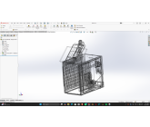
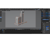
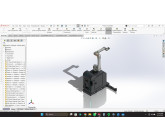
For the first round, please submit a high-level concept: 3D render(s) showing the overall shell from the front and a three-quarter/isometric view, the front LED status zones, where the access door sits, and one view showing the robot folded down (and back) in its shipping position with clear clearance from the shell. Native CAD files are not required at this stage, but the renders must come from an actual 3D model you built (Fusion 360, Rhino, SolidWorks, Blender, whatever you're comfortable with). Please also include one plain wireframe or clay/matcap viewport screenshot alongside your final render, as proof the model is real and not just an AI-generated image.
Entries that are purely AI-generated images with no real 3D model behind them will not be eligible.
Company Logo:
Yes
Software:
- SolidWorks
- KeyShot
- Blender
- Fusion 360
- Rhino
 Prepaid Prize
Entries
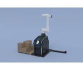
1st Winner
#21 Palletizing Robot Cell #2
by Design And More
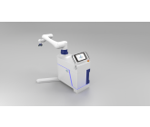
2nd Winner
#26 Concept 05
by Jinen Sheth
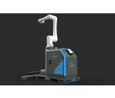
3rd Winner
#22 R PROBOT 1
by lawrence2design
Download Files
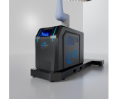
#12 Robot Cell New Exterior Design
by HandouQa
Download Files
#24 Concept 03
by Jinen Sheth
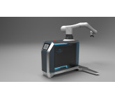
#25 Concept 04
by Jinen Sheth
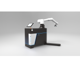
#19 Exterior Redesign of an Industrial Palletizing Robot Cell
by Busyb
Declined
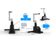
#16 Next-Gen Mobile Collaborative Palletizing Robot Cell Platform
by murat-akçtş
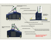
Download Files
- SolidWorks 2022 — MR- L EKLEND RMEMontaj
- SolidWorks 2022 — MR-KASA L EKLEND RME-Montaj
- SolidWorks 2022 — MR8.Montaj ZGARA -1
- SolidWorks 2022 — MR7.Main-Body-Frame-Montaj
- SolidWorks 2022 — MR6.Main-Body-Frame-Montaj
- SolidWorks 2022 — MR5.Main-Body-Frame-Montaj
- SolidWorks 2022 — MR4.Main-Body-Frame-Montaj
- SolidWorks 2022 — MR3.Main-Body-Frame-Montaj
- SolidWorks 2022 — MR2.Main-Body-Frame-Montaj
- SolidWorks 2022 — MR1.Main-Body-Frame-Montaj
- SolidWorks 2022 — MR.PBS Main Chassis Frame
- SolidWorks 2022 — MR.Main-Body-Frame-Montaj
- SolidWorks 2022 — MR.BASE CHECKER PLATE-Montaj
- SolidWorks 2022 — Ekran g r nt s 2026-07-23 032252
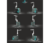
#32 R PROBOT 2
by lawrence2design
Download Files
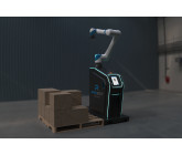
#11 ProBot Concept design
by Jinen Sheth
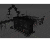
#9 iprc03
by DaBu
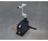
#5 Palletizing Robot Cell #1
by Design And More
Download Files
#39 Concept 06
by Jinen Sheth
#13 iprc04
by DaBu
Declined
Download Files
#29 PROBOT KINETIC : Redefining the Palletizing Cell: Modular, Ergonomic, Production-Ready
by kasturiep
Declined
Download Files
- Creo Parametric, solid works 2026 — Probot Kinectic
- Creo Parametric, solid works 2026 — Screenshot 2026-07-31 025620
- Creo Parametric, solid works 2026 — Screenshot 2026-07-31 025705
- Creo Parametric, solid works 2026 — Screenshot 2026-07-31 025740
- Creo Parametric, solid works 2026 — Workspace 1
- Creo Parametric, solid works 2026 — Workspace 2
- Creo Parametric, solid works 2026 — Workspace 3
- KeyShot 3D Rendering 2026 — KS 298395681 312-Picsart-AiImageEnhancer
- KeyShot 3D Rendering 2026 — KS 298395781 324-Picsart-AiImageEnhancer
- KeyShot 3D Rendering 2026 — KS 298395781 326-Picsart-AiImageEnhancer
- KeyShot 3D Rendering 2026 — KS 1627612106 320-Picsart-AiImageEnhancer
- KeyShot 3D Rendering 2026 — KS 1627612106 321-Picsart-AiImageEnhancer
- KeyShot 3D Rendering 2026 — KS 6387523135 335-Picsart-AiImageEnhancer
- KeyShot 3D Rendering 2026 — KS 6387523135 336-Picsart-AiImageEnhancer
- KeyShot 3D Rendering 2026 — KS 6387523135 337-Picsart-AiImageEnhancer
#8 Robot cell
by clintsar
Declined
Download Files
#35 Exterior Redesign of an Industrial Palletizing Robot Cell
by Busyb
Declined
Download Files
#36 PROBOT KINETIC : Redefining the Palletizing Cell: Modular, Ergonomic, Production-Ready
by kasturiep
Download Files
- Adobe PDF Pro 2026 — Probot Kinectic
- Creo Parametric 2026 — KS 290857798 345-Picsart-AiImageEnhancer
- Creo Parametric 2026 — KS 346549228 346-Picsart-AiImageEnhancer
- Creo Parametric 2026 — KS 614016099 350-Picsart-AiImageEnhancer
- Creo Parametric 2026 — KS 661923397 354-Picsart-AiImageEnhancer
- Creo Parametric 2026 — KS 2249318338 352-Picsart-AiImageEnhancer
- Creo Parametric 2026 — KS 2900526562 347-Picsart-AiImageEnhancer
- Creo Parametric 2026 — KS 2900526562 347-Picsart-AiImageEnhancer
- Creo Parametric 2026 — KS 4322928593 353-Picsart-AiImageEnhancer
- Creo Parametric 2026 — KS 4495010133 340-Picsart-AiImageEnhancer
- Creo Parametric 2026 — KS 5422730623 351-Picsart-AiImageEnhancer
- Creo Parametric 2026 — KS 5478412161 348-Picsart-AiImageEnhancer
- Creo Parametric 2026 — KS 5478423861 341-Picsart-AiImageEnhancer
- Creo Parametric 2026 — KS 5478423861 342-Picsart-AiImageEnhancer
- Creo Parametric 2026 — Screenshot 2026-08-04 133214
- Creo Parametric 2026 — Screenshot 2026-08-04 133253
- Creo Parametric 2026 — Screenshot 2026-08-04 133702
- Creo Parametric 2026 — Screenshot 2026-08-04 133739
- Creo Parametric 2026 — Screenshot 2026-08-04 133816
#10 Robotic Palletizer Cell
by Dyhas-130
Declined
Download Files
#2 PROBOT Nova
by mechanical_3d
Declined
Download Files
#27 Probot
by mechanical_3d
Declined
Download Files
#43 PROBO Smart Palletizing Cell
by ibikiris
Declined
#7 VECTOR ONE – Next-Generation Industrial Palletizing Robot Cell
by lekang
#6 ProBot X1 Fusion
by NextGen_IoT_LAB
#1 Probot Exterior Design Concept
by Jinen Sheth
Declined
Download Files
#61 robot cell
by swati
Declined
Download Files
#51 Industrial Palletizing Robot Cell
by Vrajgbu
Declined
Download Files
#52 Monolith robot cell by sirchulle
by sirchulle
Download Files
- 3D Blender — VIDEO 1
- 3D Blender — 2026-08-10 20-50-14
- 3D Blender — 2026-08-10 20-52-23
- 3D Blender — 2026-08-10 20-57-03
- 3D Blender — BACK VIEW
- 3D Blender — BACK VIEW INETRIOR
- 3D Blender — FRONT VIEW
- 3D Blender — LATE NIGHT SHIFT COOL PATTERN
- 3D Blender — SIDE VIEW COOL PATTERN
- 3D Blender — SIDE VIEW COOL PATTERN CLOSE
- 3D Blender — VIEW
#53 proto_before_final
by adamrockler
#54 R PROBOT 3
by lawrence2design
Download Files
#55 Exterior Redesign of an Industrial Palletizing Robot Cell
by Inerapello
Download Files
#56 Exterior Redesign of an Industrial Palletizing Robot Cell
by Inerapello
Declined
Download Files
#73 Exterior Redesign of an Industrial Palletizing Robot Cell
by Azadservice
Download Files
#57 Exterior Redesign of an Industrial Palletizing Robot Cell-C1
by alirezaemamian
Declined
Download Files
#58 Exterior Redesign of an Industrial Palletizing Robot Cell
by vsnmechdesign
Declined
Download Files
- 3D Solidworks — full project
- 2D & 3D Modeling Solidworks — wireframe with FANUC R-30iB Mini Plus Controller Cabinet
- 2D & 3D Modeling Solidworks — back
- 3D Solidworks — bottom
- 3D Solidworks — dimetric
- 2D & 3D Modeling Solidworks — fold position
- 3D Solidworks — front
- 3D Solidworks Professional — isometric
- 3D Solidworks — left
- 3D Solidworks — open position
- 3D Solidworks — right
- 2D & 3D Modeling Solidworks — side service panel
- 2D & 3D Modeling Solidworksp — top
- 3D Solidworks — trimetric
#59 Exterior Redesign of an Industrial Palletizing Robot Cell final
by Busyb
#60 PROBOT CRX-30iA — Next-Gen Collaborative Palletizing Cell
by ghaichateo
#66 اندرويد
by faris
Declined
Download Files
#72 Exterior Redesign of an Industrial Palletizing Robot Cell
by Kzswara
Download Files
#62 Exterior Redesign of an Industrial Palletizing Robot Cell.................................................................................................................
by vsnmechdesign
Declined
Download Files
- 3D Solidworks — full project proof
- 3D Solidworks — wireframe with FANUC R-30iB Mini Plus Controller Cabinet
- 2D & 3D Modeling Solidworks — back
- 2D & 3D Modeling Solidworks — bottom
- 2D & 3D Modeling Solidworks — dimetric
- 2D & 3D Modeling Solidworks — fold position
- 3D Solidworks — front
- 3D Solidworks Professional — isometric
- 3D Solidworks — left
- 2D & 3D Modeling Solidworksp — open position
- 3D Solidworks Professional — side service panel
- 2D & 3D Modeling Solidworks — right
- 2D & 3D Modeling Solidworksp — top
- 2D & 3D Modeling Solidworks — trimetric
- 2D & 3D Modeling Solidworks — 1
- 2D & 3D Modeling Solidworks — back1
- 2D & 3D Modeling Solidworks — bottom1
- 2D & 3D Modeling Solidworksp — dimetric1
- 2D & 3D Modeling Solidworksp — fold position1
- 2D & 3D Modeling Solidworks — front1
- 2D & 3D Modeling Solidworks —
#71 Exterior Redesign of an Industrial Palletizing Robot Cell
by Inerapello
Download Files
#63 Exterior Redesign of an Industrial Palletizing Robot Cell,,,,,,,,,,,,,,,,,,,,,,,,,,,,,,,,,,,,,,,,,,,,,,,,,,,,,,,,,,,,,,,,,,,,,,,,,,,,,,,,,,,,,,,,,,,,,,,,,,,,,,,,,,,,,,,,,,,,,,,,,,,,,,,,,,,,,,,,,,,,,,,,,
by vsnmechdesign
Declined
Download Files
- 2D & 3D Modeling Solidworks — back
- 3D Solidworks — bottom
- 2D & 3D Modeling Solidworks — dimetric
- 2D & 3D Modeling Solidworksp — fold position
- 3D Solidworks — front
- 3D Solidworks Professional — isometric
- 2D & 3D Modeling Solidworksp — left
- 2D & 3D Modeling Solidworks — open position
- 3D Solidworks — right
- 2D & 3D Modeling Solidworks — side service panel
- 3D Solidworks — top
- 2D & 3D Modeling Solidworksp — trimetric
- 3D Solidworks — wireframe with FANUC R-30iB Mini Plus Controller Cabinet
- 2D & 3D Modeling Solidworks — side service panel1
- 2D & 3D Modeling Solidworks — proof1
- 3D Solidworks — 2
- 3D Solidworks — wireframe1
- 3D Solidworks Professional — fold position2
- 2D & 3D Modeling Solidworks — open position2
- 2D & 3D Modeling Solidworksp — dimetric2
- 2D & 3D Modeling Solidworks —
#64 Next-Gen Cobot Palletizer Concept
by adrianb6
Declined
Download Files
#70 Probot system new design
by BLADE_STYLE
#65 Exterior Redesign of an Industrial Palletizing Robot Cell
by Vrajgbu
#69 Probot
by Richard_Joe
Declined
Download Files
#68 Exterior Redesign of an Industrial Palletizing Robot Cell
by Kzswara
#67 proto_final
by adamrockler
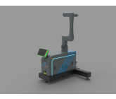
#33 Robot Cell
by ecco ww
Declined
Discussion
Showing last 20 comments - View All
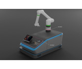
Any feedback on entry 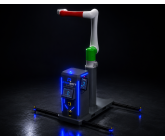 .
.
.

Thank you for reviewing my submission. I noticed the entry 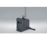 was declined and would appreciate any brief feedback on the reason so I can improve future submissions. If there were specific requirements that were not met, please let me know. Thank you.
was declined and would appreciate any brief feedback on the reason so I can improve future submissions. If there were specific requirements that were not met, please let me know. Thank you.

working on it,please wait until deadline,thanks

Just checking in to see if you have any feedback on my latest submission! I'd really appreciate a quick rating or any notes so I can fine-tune the design to perfection.
Thanks!
Thanks!
Robot must still be able to rotate fully downward into its flat shipping position, with zero collision against the new shell
Robot arm segments must also be able to fold back/rearward for a compact shipping footprint - please can you attach any image in that position thanks
Robot arm segments must also be able to fold back/rearward for a compact shipping footprint - please can you attach any image in that position thanks
any feedback on my latest entry

Hi,
Yes, the single exterior shell that encapsulates everything is a strict requirement. We do not want separate housings with a wiring channel between them.
The reference corner is a corner of the T-Base itself. The robot base should sit 24 in from that corner.
Thanks,
Yes, the single exterior shell that encapsulates everything is a strict requirement. We do not want separate housings with a wiring channel between them.
The reference corner is a corner of the T-Base itself. The robot base should sit 24 in from that corner.
Thanks,
Hi Daniel
No servo motor for us, we want to keep it simple and manual. It does not necessarily need to be telescoping either. The 81" width is approximate, so you have some flexibility there. What matters most is that the outriggers provide solid, reliable stability once in place, and that the legs can be removed or repositioned for transport. The cotter pin and hole assembly works fine for that. Feel free to propose the simplest design that achieves good stability.
Thanks,
No servo motor for us, we want to keep it simple and manual. It does not necessarily need to be telescoping either. The 81" width is approximate, so you have some flexibility there. What matters most is that the outriggers provide solid, reliable stability once in place, and that the legs can be removed or repositioned for transport. The cotter pin and hole assembly works fine for that. Feel free to propose the simplest design that achieves good stability.
Thanks,

The T-Base has a width of 81"; are you against the idea of the outrigger leg supports being mechanically raised and lowered by a servo motor; or would you rather have telescoping 'extendable' outrigger supports with standard cotter pin, and hole assembly to make the support legs (removable/repositionable) during transport/shipping/relocating?

1. Is the exterior shell that encapsulates everything a strict requirement, or is it possible to have one housing for the electrical panel and the robot controller (or maybe separate housing for both), and a separate robot base column/tower (like shown in the AI-generated concepts) with a channel between the two for wiring?
2. The requirements mention that the robot base should sit 24 in from the reference corner. What does it refer to? I cannot seem to find where the reference corner is shown.
2. The requirements mention that the robot base should sit 24 in from the reference corner. What does it refer to? I cannot seem to find where the reference corner is shown.

Bonjour Pierre, Etienne et Germain,
I have submitted an entry ( ), would like to know if it meets your expectations. Regards
I have submitted an entry (
), would like to know if it meets your expectations. Regards
● Does the base need to remain a literal “T” shape, or is any shape acceptable as long as it fits inside the width/length/height/leg-span envelope?
It's probably best for a T shape but I'm open to some idea.
● Is there a target pallet-jack fork spacing/size (standard 27–28 in fork centers) we should design the base openings around?
yes 27-28 inch for pallet jack
● Is the 81 in deployed outrigger width a hard target, or can it be reduced if structurally justified?
can be reduce if you can make it.
It's probably best for a T shape but I'm open to some idea.
● Is there a target pallet-jack fork spacing/size (standard 27–28 in fork centers) we should design the base openings around?
yes 27-28 inch for pallet jack
● Is the 81 in deployed outrigger width a hard target, or can it be reduced if structurally justified?
can be reduce if you can make it.

● Does the base need to remain a literal “T” shape, or is any shape acceptable as long as it fits inside the width/length/height/leg-span envelope?
● Is there a target pallet-jack fork spacing/size (standard 27–28 in fork centers) we should design the base openings around?
● Is the 81 in deployed outrigger width a hard target, or can it be reduced if structurally justified?
● Is there a target pallet-jack fork spacing/size (standard 27–28 in fork centers) we should design the base openings around?
● Is the 81 in deployed outrigger width a hard target, or can it be reduced if structurally justified?

"Hi everyone! Happy to join the contest with Entry  . Wishing the best of luck to all the talented designers here!"
. Wishing the best of luck to all the talented designers here!"
FANUC R-30iB Mini Plus Box: Should the FANUC controller box sit completely hidden inside our exterior sheet metal cabinet (behind a hinged access door with air vents), or do you want the controller box itself mounted directly on the exterior / built into the outer shell? Yes it should be inside.
Outrigger Legs: Do you prefer manual swing-out legs (simple, robust, quick-locking pin) or fully pneumatic/motorized legs (automated via touchscreen)?
Manual, simple fast mechanism, no/few play.
Outrigger Legs: Do you prefer manual swing-out legs (simple, robust, quick-locking pin) or fully pneumatic/motorized legs (automated via touchscreen)?
Manual, simple fast mechanism, no/few play.



Dear pierreetiennegermain. I'm working on your project now. Almost done.
I'll share result as soon as possible.
Best Reagrds
Thi Vu
I'll share result as soon as possible.
Best Reagrds
Thi Vu
Hi pierreetiennegermain ,
Could you please clarify two quick setup details for the design?
FANUC R-30iB Mini Plus Box: Should the FANUC controller box sit completely hidden inside our exterior sheet metal cabinet (behind a hinged access door with air vents), or do you want the controller box itself mounted directly on the exterior / built into the outer shell?
Outrigger Legs: Do you prefer manual swing-out legs (simple, robust, quick-locking pin) or fully pneumatic/motorized legs (automated via touchscreen)?
Thanks!
Could you please clarify two quick setup details for the design?
FANUC R-30iB Mini Plus Box: Should the FANUC controller box sit completely hidden inside our exterior sheet metal cabinet (behind a hinged access door with air vents), or do you want the controller box itself mounted directly on the exterior / built into the outer shell?
Outrigger Legs: Do you prefer manual swing-out legs (simple, robust, quick-locking pin) or fully pneumatic/motorized legs (automated via touchscreen)?
Thanks!
I have added STEP file of the real robot, the robot controler, the electrical panel as well as the safety sensor.
working on it,please wait until deadline,thanks
Yes for Step, I dont have Catia but yes you can make it. Goal for now is more having ideas and new concept.
Similar Contests on Cad Crowd
Processing Unit
Designing, detail engineering and submission of design, general arrangement, fabrication detailed drawings and 3d model
of a continuous process, fully automated controlled Pilot unit for the capacity of 50 to 75kg.hr feed stock MSW plastic
waste processing at high temperature & oxygen free with atm pressure.
Soft close, no pinch safety hinge
We are a company that provides innovative product solutions for the physical education and educational market. We pride ourselves in providing the most innovative, high quality product to our customer. This product would be a soft close, safety hinge used to hold the lid open on our line of ball carts. It needs to be pressure sensitive and stay open at any angle and not slam closed. It also must not have any pinch points where the fingers could get pinched. The lid would need to be pushed closed by the user. The lid itself that needs to be supported is about 25lbs., however, the hinge would need to support more in order to keep it from closing on it's own. The end user can be a student so safety is critical. There are many soft close hinges on the market, many with pneumatic functionality and gas hinges and often used on toy boxes. I have attached a photo of an existing hinge on the market just for reference. I am open to materials based on design and likely will need to be pneumatic or incorporate a gas hinge. I have included a link to our website to see the carts it would be used on. You can also see a few of the existing hinges that have been/are being used that I am looking to update with a better hinge. I am also including files to the carts themselves so you can see the product the hinge will be used on, as well as instructions that show the current hinge being used that I am looking to update. The existing hinge is not ideal as there are potential pinch points.
https://www.gophersport.com/supplies/storage/titan-ball-carts?item=6397
Segmented Connect-a-Hoop
We are a company that provides innovative product solutions for the physical education and educational market. We pride ourselves in providing the most innovative, high quality product to our customer. This product would be a segmented hula hoop that consists of multiple segments that connect together, allowing the user to create 3 different size hoops based on the number of segments used. This allows the user to build the hoops size they choose. The key factor in this design is to have a unique, innovative connection point that is easy to put together and take apart, holds the hoop securely together when in use and will not become weak or break when used repeatedly in an institutional setting. The connection point must be able to be taken apart and put back together an indefinite number of times without the strength being jeopardized.
Modern desk lamp made of carbon fiber
Space Division Inc is inspired by space travel and the materials used to make modern rockets and space ships. We want to design office furniture that embodies this inspiration and makes use of this material. We are set to launch a sit/stand desktop converter called the Booster and now we want to provide additional, complimentary products. The first is a modern, space inspired desk lamp.
Elecyr Hybrid Energy Storage System
Our products connect directly to solar panels or the grid and store energy to provide power at a later time. They can be interconnected to form a microgrid and share the power collected among multiple systems. Our current product starts at 15kW, weighs about 700lbs and can be expanded to a megawatt. We are developing a family of lower end systems starting at 2500 watts and weighing less than 100 lbs. We're looking for a consistent, modern, clean and attractive look that will bridge the range of products and be sufficiently visually striking to help with our entire company identity. We're looking for a clean functional design that's very simple. Think iPhone and Cuisinart. We also would like to minimize tooling costs and keep the cost of the packaging as low as possible. We have a mechanical design team so we're primarily looking for a conceptual design look rather than a detailed package. I've attached a couple images of our existing power stack and a possible design for the 2.5kW 100 lb unit. 605×330×445 mm (LWH). We are also looking to do a scaled up unit at 5kW that's also portable and a more fixed unit at 8kW that is more like the large system we have now. I've attached a sketch of how that one will assemble internally. Again, we're looking for someone to bring a consistent, recognizable and unique look to the product line while staying very simple and clean.
clintsar
Designer