Motion tracker unit with holder
in
Product Design
held by
Meshtech
Last seen:
Contest Ended, Winner(s) have been selected.
-
Open
-
Choosing Finalist
-
Ended
Description:
We are looking to develop product design drawings to be used for manufacturing of our motion tracker unit, which will be launched for a fitness center chain, for tracking use of exercise machines. The unit will house our own electronic module and battery, so the design shall result in the required 3D production drawings for plastic molding of the unit housing (stp or dwg file format), which will be in two parts (top + bottom), and a matching holder.
Detailed descriptions (dimensions and considerations) are enclosed in a separate document, to be considered as guidelines with some freedom for the designer.
Wants:
Need to meet the technical specification attached, and designs will be evaluated based on esthetics and functional cleverness.
Don't Wants:
I don't want an exact copy of the suggestion in the attached document. Feel free to make a pleasant design while maintaining the functional properties.
Company Logo:
Yes
Software:
- .STP - Step 3D CAD
Additional Information
12.05.2017: Update on contest - We realize that demanding production drawings for the molds to produce the plastic parts forming the motion tracker unit and holder is too much. So we will only require 1 set of drawings, for the 3D design of the product. I have updated the description below (under 02.05.2017 update). Apart from that, we have now finally given ratings to all contributors, and nominated what we think are the best overall designs so far, with emphasis on visual design as well as function.
We are a small and fairly new technology company, with a lot of activity so apologies for late feedbacks, answers and ratings - we just have a lot to do running the business as well as developing new products. Thanks for all inspiring contributions so far, and I shall look forward to seeing some further developed designs next week!!
03.05.2017: One tip regarding the "push button". As it may compromise the integrity against water ingress to introduce a physical button as a separate part/component, it is possible to achieve pushing ability on the center of the top section introducing a circular zone with a slightly thinner wall thickness, and with a centered pin on the interior side which will operate the switch on the PCB. The top section surface can then be completely smooth.
02.05.2017: Updated and uploaded revised requirements file. Mainly document structure and dimensions update. You should note requirement 0021, which will give constraints on the design for keeping the motion tracker in the holder:
[MT3001-REQ-0021] Retaining Motion Tracker in Holder
The Holder shall keep the Motion Tracker inside the Holder when applied of forces at least 5G.
The manufacturing process of the final design will be molding of three plastic parts (upper + lower part of the tracking unit and the holder), not 3D printing.
We want 1 set of drawings:
for 3D design of the product (including all dimensions with engineering units)
1. detailed view of each of the three parts separately
2. assembled unit
3. unit inserted in holder
4. Plus for adding design for the interior and clever solutions for 'pushbutton functionality' without physical pushbutton, no holes in the housing for tracker unit, light indication facilitated using thinner wall thickness in center of top part (in PB function area), and only screw hole in holder.
 Prepaid Prize
Entries
1st Winner
#41 Motion Tracker & Holder
by Indrawan

#33 Motion Tracker Unit with Holder
by SaketCad

Download Files
- SolidWorks 2012 — Motion tracker modified Render-tile
- SolidWorks 2012 — Motion tracker modified section view front plane
- SolidWorks 2012 — Motion tracker modified Exploded
- SolidWorks 2012 — Motion tracker unit modified - top shell
- SolidWorks 2012 — Motion tracker unit modified -Bottom shell
- SolidWorks 2012 — Motion tracker unit modified -Holder
#31 Motion Tracker & Holder
by Indrawan

Download Files
#28 Tracker 2.5
by ;lzsvpja-] bja]=

#38 MeshTech-Motion Tracker Concept 1
by Pablo Gosso

#51 Motion Tracker Unit with Holder
by SaketCad

Download Files
- SolidWorks 2012 — Motion tracker unit modified-1 render-tile
- SolidWorks 2012 — Motion tracker unit modified-1 Bottom shell-1
- SolidWorks 2012 — Motion tracker unit modified-1Holder-1
- SolidWorks 2012 — Motion tracker unit modified-1Top Shell-1
- SolidWorks 2012 — Motion tracker unit modified-1 Bottom shell.DRW
- SolidWorks 2012 — Motion tracker unit modified-1Holder drw.
- SolidWorks 2012 — Motion tracker unit modified-1Top shell drw.
#42 Motion Tracker Unit with Holder
by SaketCad

Download Files
#18 Motion tracker unit with holder
by Ahmed Youssef

#15 Motion tracker unit with Holder
by SaketCad

#17 Tracker 2.0
by ;lzsvpja-] bja]=

Download Files
#27 Motion Tracker & Holder
by Indrawan

Download Files
#36 motion tracker ad03 - Adriano Barissa
by Adriano Ordoz Barissa

#37 Motion tracker unit with holder
by Ahmed Youssef

#40 Bottom half of Motion Tracker housing 4.1
by Ahmed Youssef

Download Files
#21 Motion Tracker 4.0
by Adam

Download Files

#1 Enclosure Concept A
by Decker

Download Files
#3 Motion Tracker
by ;lzsvpja-] bja]=

#4 Concept Design Layout - Rev B
by Decker

Download Files
#5 Tracker 1.0
by ;lzsvpja-] bja]=

#53 Motion Tracker Unit With Holder V2.0
by ProDes Solutions

Download Files
#49 Motion tracker AD04 Rev02 - Adriano Barissa
by Adriano Ordoz Barissa

#47 motion tracker ad04 - Adriano Barissa
by Adriano Ordoz Barissa

#13 Motion tracker unit with holder
by Ahmed Youssef

Download Files
#14 Motion tracker unit with holder
by Ahmed Youssef

Download Files
#39 Motion tracker unit with holder
by sherifelsheikh

#44 Motion Tracker & Holder
by Samadoni

Download Files
#54 MESHTECH-MOTION TRACKER-RENDER-MOD B.2
by Martin Arguello

Download Files
#46 Mold-Insert CAD for submsn #44
by Samadoni

#35 the glass eye
by Manuel Zaragoza

#34 The glass eye
by Manuel Zaragoza


#30 MESHTECH-MOTION TRACKER-MOD B
by Martin Arguello

Download Files
#2 MOTION-TRACKER 1.0
by Adam

Download Files
#6 Motion Tracker 2.0
by Adam

#7 Tracker 1.5
by ;lzsvpja-] bja]=

Download Files
#8 Simply
by REDA

Download Files
#16 MotionTrak 3.0
by Adam

#19 Concept
by handsketcher

Download Files
#20 MAXIMUM OUTER DIAMETER ISSUE
by Adam

#23 sensor ad01 - by Adriano Ordoz Barissa
by Adriano Ordoz Barissa

Download Files
#24 sensor-ad001 - by Adriano Ordoz Barissa
by Adriano Ordoz Barissa

#26 sensor ad02 - by Adriano Ordoz Barissa
by Adriano Ordoz Barissa

#32 Motion tracker unit with holder
by REDA

Download Files
#22 Motion tracker unit with holder
by REDA

Download Files
#43 Motion tracker unit with holder
by sherifelsheikh

Download Files
#12 Motion tracker unit with holder
by REDA

Download Files
#11 Motion tracker unit with holder
by REDA

Download Files
#10 Motion tracker unit with holder
by REDA

Download Files
#50 Motion Tracker Unit With Holder
by ProDes Solutions

Download Files
Discussion
Hello again gents!
My final comment to this contest, as we have now announced the winning design. It was a difficult task to choose between so many very different good designs, and a learning process for our part. So many inspiring and interesting designs to go through. Well done everyone, and thanks for participating and submitting your ideas, it has been a pleasure and a lot of fun! See you next time, and keep up the creative spirits!
BRgds,
Preben G. Skretteberg
Project Manager, Meshtech.

Note: Not sure why some of the design pictures turned up in my message, pls disregard, this is not the finalists.
Gents, first og all thank you to everyone for your contributions to the contest !!
We are overwhelmed with all the entries and different designs sent in by you. The contest is now finished (as per 26th of May), however we have not yet concluded on the winning design.
The entries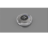 to
to 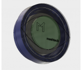 are reviewed and rated, the remaining ones from
  to
to  are still in review. We will however focus our work on the improved designs that we have already commented on, but will still be open to single entry designs.
I really want to do justice to all contributions, and take some time to review in detail, this is one of the reasons that ratings and response has been a bit slow on our side.
Nevertheless, we are in dialogue with a production facility which will manufacture our tracker unit, and the winning design from CadCrowd contest will be the design sent to fabrication (which will be one more process with possible adjustments to facilitate serial production).
So, I will get back to you with the final decision and reward for winning design, please be patient a little longer.
BRgds,
Preben G. Skretteberg
Project Manager, Meshtech AS.
We are overwhelmed with all the entries and different designs sent in by you. The contest is now finished (as per 26th of May), however we have not yet concluded on the winning design.
The entries
to are reviewed and rated, the remaining ones from to are still in review. We will however focus our work on the improved designs that we have already commented on, but will still be open to single entry designs. I really want to do justice to all contributions, and take some time to review in detail, this is one of the reasons that ratings and response has been a bit slow on our side.
Nevertheless, we are in dialogue with a production facility which will manufacture our tracker unit, and the winning design from CadCrowd contest will be the design sent to fabrication (which will be one more process with possible adjustments to facilitate serial production).
So, I will get back to you with the final decision and reward for winning design, please be patient a little longer.
BRgds,
Preben G. Skretteberg
Project Manager, Meshtech AS.

To the winner Congrats!!

Hi Preben,
Please rate the designs.
Rgds,
STL
Please rate the designs.
Rgds,
STL

As for Pablo Gosso's idea, I 2nd that ...
Securing the unit via Nd-mag would be my first choice for this particular application. It would drastically cut-down tooling costs.
Securing the unit via Nd-mag would be my first choice for this particular application. It would drastically cut-down tooling costs.
Hi Pablo,
Thanks for an interesting suggestion. This has been considered, the problem with this is that using a magnet will impact the radio communication between the tracker and our gateway, so this was ruled out as not suitable. But apart from that you are correct.
As primary fixing we will use double-sided adhesive tape, and screw holes are just as secondary solution if not possible to glue.
BRgds,
Preben
Hi Preben.
One question Instead of Holder and screw would you be willing to use Neodimiun Magnets?. It is just and Idea that I ould like to try and according to specs they a hold 5g. Plus you will be decreasing mold/tool budget?
Pablo
One question Instead of Holder and screw would you be willing to use Neodimiun Magnets?. It is just and Idea that I ould like to try and according to specs they a hold 5g. Plus you will be decreasing mold/tool budget?
Pablo
Hi STL,
you are right, apologies. Pls see below.
1.Mounting holes on PCB with location are missing , we require those for designing lower shell.(Mounting Boss).
>> The PCB is still under development, so exact location is not so important, however the principle can be shown (we can even adapt PCB to suit your location of mounting pins.
2.Location & no. of LED lights on tracking unit for thin area on holder for visibility of LED lights
>> The best would maybe be a semi-transparent material which will show the light shining through the plastic. It is not necessary to have a very clear view of the light, only a "glow" is sufficient. However I would suggest LED should be located centrally on the top.
Hello preben,
Thanks for the reply, but you have not clarified our last two points.
Rgds,
STL
Thanks for the reply, but you have not clarified our last two points.
Rgds,
STL
Hi STL, the top and bottom will not be same and need different mold, that is correct. Initially we thought it might be possible, however just disregard previous comments and questions related to using same mold for top and bottom.
Seems you are correct related to the RAL9003, the initial color was in different coding from our graphic designer and using a conversion tool online suggested RAL9003 to be the closest match in the RAL color coding scheme. It really is not that important for the product design drawings at this stage - pale grey or white will do.
Trust this clarifies.
BRgds,
Preben
Hi Preben,
Kindly clarify following points,
If top & bottom shell will be threaded then the mold will not be same.Even if any other joining method is used the bottom shell will have mounting boss for PCB so the molds will be different.
RAL Color mentioned is RAL 9003 which is signal white & not grey as mentioned in your document,
Mounting holes on PCB with location are missing , we require those for designing lower shell.(Mounting Boss).
Location & no. of LED lights on tracking unit for thin area on holder for visibility of LED lights.
Rgds,
STL
Hi STL, the gap between holder and tracker unit is intended to pry the unit out from the holder using e.g. a screwdriver. It should be sufficient with approx 1mm gap.
BRgds,
Preben
BRgds,
Preben
Hi,
Refer figure 2 in the specification sheets attached.Any specific requirement for the gap between bottom of the motion tracker unit & the holder.
Rgds,
STL
Refer figure 2 in the specification sheets attached.Any specific requirement for the gap between bottom of the motion tracker unit & the holder.
Rgds,
STL
Hi Samadoni,
the PCB is also under development, so this is not concluded I'm afraid. However, the button/switch will in any case be in the center. Will post an update once this is ready.
the PCB is also under development, so this is not concluded I'm afraid. However, the button/switch will in any case be in the center. Will post an update once this is ready.
Hi Preben,
A drawing of the PCB outline with dimensions would help a lot, especially if it shows:
1) Number and location of the LED's, & button.
2) Fastening holes/notches locations.
A drawing of the PCB outline with dimensions would help a lot, especially if it shows:
1) Number and location of the LED's, & button.
2) Fastening holes/notches locations.

thanks for the description, i am working on it.
Hi Ghufran,
Thanks for your question. The manufacturing process will be molding of three plastic parts (upper + lower part of the tracking unit and the holder), not 3D printing. We want 2 sets of drawings, one for 3D design of the product (detailed view of each of the three parts separately as well as assembled and inserted in holder), and one for manufacturing of the molds to produce the product (if possible to use same mold for upper and lower part of tracking unit that's great, and one for mold to produce holder).
I will add this into the description of the contest.
Thanks again,
Preben
Meshtech, Project Manager
hello,
kindly confirm
as far i have understand you only want drawing for manufacturing, or you need model for 3d Printing as well?
kindly confirm
as far i have understand you only want drawing for manufacturing, or you need model for 3d Printing as well?
Similar Contests on Cad Crowd
Need 3D Design and CAD for Toy Helicopter - New Product Prototype
We are a manufacturer of Remote Control Toys. We are looking to design a line of flying animals using the base of a current helicopter (attached are pics). We will need the designer to design the outside body in the shape of a Pig, Making a remote control flying pig. The landing gears can be taken off, and the pig will encompass the whole helicopter body. Please submit design 3D design work for a flying Pig.
Electrical roller door
Design an electrical roller door using neoprene or similar material for door.
Roller at top.
Design a next generation, WiFi controlled sprinkler unit
We are building a WiFi enabled irrigation unit and need a prototype 3D design that we will print.
Here is our company www.h2lo.co
I have included these photos just to show what the slot on the bottom will look like for the consumer to attach wires to the sprinkler relay.
http://rayshobby.net/wordpress/wp-content/uploads/2013/03/IMG_2424-300x200.jpg
http://rayshobby.net/wordpress/wp-content/uploads/2013/03/IMG_2425-300x200.jpg
http://rayshobby.net/wordpress/wp-content/uploads/2013/03/IMG_2426-300x200.jpg
This design will encase a PCB board with a relay.
quadcopter UAV design contest
I need a unique, rugged quadcopter UAV design,analysis and all necessary fabrication details for production in large quantities.The quadcopter should have a high endurance similar to the Microdrones Md4-1000
LINK:
(http://www.microdrones.com/products/md4-1000/md4-1000-key-information.php#what)
The quadcopter should be modular in nature like the Aeryon Scout
LINK:
Scout(http://ww1.prweb.com/prfiles/2010/09/01/3259734/MG1969.JPG)
NEEDS:
good aesthetic design,analysis along with all production details,
modular nature,
Materials used,
Sourcing details,
Bill of materials(BOM)
Control-box with display, fitting on a DIN rail
This is about a first product draft, which shall later be turned into a production ready design.
I need an enclosure for a custom made electronic part. The rough form-factor should be similar to a navigation system (see attached files) with a display in front and parallel enclosure boundaries, slightly rounded edges.
The display is 4.3 inches wide (see technical details attached) and should be included in the rendering. The enclosure should be 4 cm deep.
As a bonus, the display shows attached bar diagram.
At the back, there should be the possibility for a DIN rail mount, top hat rail EN 50022 – 35 × 7.5
but also for direct wall mount using screws or mounting to a bar with cable ties.
At the front left side of the enclosure, I need a C14 inlet to add a power cable and a Schuko socket: https://en.wikipedia.org/wiki/Schuko or CEE 7/3 socket. See attached figure of the design.
The material should be dark grey with a bit reflective surface. Please add our logo to the upper left corner of the front, below the display. If it fits optically, it could glow a bit in green.
Meshtech
Buyer