Mechanical Engineer to develop light guides or light pipes used with LEDs
in
3D Modeling Design
held by
jflagle
Last seen:
Contest Ended, Winner(s) have been selected.
-
Open
-
Choosing Finalist
-
Ended
Description:
Looking for an engineer that has experience with light guides or light pipes used with LEDs, and that can design a few simple light guides for an electronic device. 3 LEDs - red, green, blue will feed the light pipe. the other end of the light pipe will be visible to the user thorugh a cutout in the enclosure. the user will see this end of the light pipe, which is 2 strips each at .2 wide x 2" long. there may be some curvature to these 2" long strips (maybe a radius of 2.5"). when the red LED is on the strips will light up red. same for green, etc. need to make sure the lighting is continuous (not brighter at one end than the other). Proven experience with LIght pipes is required. $100 for initial sketch and background proving that this design will work. Further work would then be given to winner to develop the concept into a injection molded part. Good Luck and I look forward to working with you.
Wants:
light pipe design must be able to be converted into an injection molded light guide with a cost of less than 1.00 per part at 1000pc lot size. needs to be assembly sketch with lightpipes and LEDs, and part sketches for each light pipe. see attached pg2. sketch with dimensions, material, and engineering proof (design guides, other similar products, prior experiences, etc) that the concept will work. Bonus points will be given to designs turned in by 9/21/2016
Software:
- SolidWorks
Additional Information
Any design must inlcude the following for consideration: 1) the concept must include sketch/model of the actual light guides with dimensions, and any surface treatments etc. and sketch/model of the assembly showing how they are held to circuit board and housing.
 Prepaid Prize
Entries
1st Winner
#2 light-pipe
by Adam

Download Files
#10 LIGHT GUIDE_UPDATE
by 25ART

#1 Alarm
by John Paulo

Download Files
#3 Light guides
by Aminegn

Download Files
#4 Light guides
by Aminegn

Download Files
#5 Light pipes used with LED
by Bodhayan

Download Files
#6 Lightpipe
by Adam

Download Files
#7 Mechanical Engineer to develop light guides or light pipes used with LEDs.rev1
by Michael Dimou

#8 Light guides
by Aminegn

Download Files

#11 light guide
by MR. CAD DESIGNS

Discussion
i would like to choose 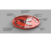 light-pipe by Adam as the contest winner. however, teh website will not allow me to select the winner at this point. i am still wihting the 7 days of contest ending.
runner up would be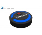 LIGHT GUIDE_UPDATE by 25@rt
cadcrowd admin - can you please select this winner for me...
light-pipe by Adam as the contest winner. however, teh website will not allow me to select the winner at this point. i am still wihting the 7 days of contest ending. runner up would be
LIGHT GUIDE_UPDATE by 25@rtcadcrowd admin - can you please select this winner for me...

 please save as a step file or other format that can be opened in SW 2016 or send jpegs
 Any design must inlcude the following for consideration: 1) the concept must include sketch/model of the actual light guides with dimensions, and any surface treatments etc. and sketch/model of the assembly showing how they are held to circuit board and housing.

please save as solidworks 2015 or earlier, or as a step file.
Note: Any design must inlcude the following for consideration: 1) the concept must include sketch/model of the actual light guides with dimensions, and any surface treatments etc. and sketch/model of the assembly showing how they are held to circuit board and housing.
I cannot open the file. I am using solidworks 2015. please save as SW 2015 or a step file.
Note: Any design must inlcude the following for consideration: 1) the concept must include sketch/model of the actual light guides with dimensions, and any surface treatments etc. and sketch/model of the assembly showing how they are held to circuit board and housing.

Please tell us if our designs are correct or need some improvements .
Thanks.
Thanks.
I would recommend a light pipe that lights up the entire Square that company name is on, and then company name is just pad printed in Black Ink. Also, you are correct. There will be a mute button on the printed circuit board. At this point we can use any button. Feel free to recommend any button and light combination.

The company name must be one continuous opening, so letters "A", "O', "D" etc. are not feasible as a cut-out for the lightpipe on the top housing.
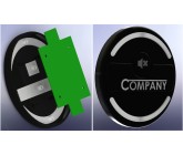
What feature on the board actuates "mute on", "mute-off". Typically a button such as this is a separate molded part with a small light pipe inside along with a spring and features on the housing to accommodate it.
What feature on the board actuates "mute on", "mute-off". Typically a button such as this is a separate molded part with a small light pipe inside along with a spring and features on the housing to accommodate it.
Similar Contests on Cad Crowd
SolidWorks Simple Box with 2 Cords - Freelance 3D Designer Contest
Keep the dimensions of the box exactly as they are in the 2D version (they are in imperial but can be changed to metric in the solidworks file) I'm looking for a clean 3D Solidworks file of the exterior with the 2 cords that can pull out almost to look like an assembly drawing in Solidworks. I'm not looking to get detailed on what the product is or how it will work, but the top port is a Micro USB, and the bottom port is a Lightning USB. The notches on both are for fingernails and a cord will pull out. There is a very small power button on the bottom and 4 LED lights on the back side that I will update soon. I'm looking for conceptual nice looking design to use for sale of the product.
PDF to SolidWorks
Convert PDF to Solid Works 14
Smart Wristband
I'm a tech&des student in the UK. I've been able to get by without being great at CAD but this year is unavoidable. My project is a wristband designed for old people that can track where they are and their heart rate. This project will be straight forward for anyone familiar with solid works 2013, neeed it by the next 2 days, (due on wed)
Liver Shell
Design should be of a liver shell. It should be an anatomically accurate model that can be printed if needed to. The inside should be hallow and the liver should include a hole on top where the hyper-vein would normally be and a hole on bottom where the vein would leave. The liver shell should be a 2 piece design that can be clicked/ screwed together to symmetrically put together the 2 halves.
http://www.exchange3d.com/3D-Model-of-Liver-Anatomy/prod_28235.html#preview
A more simplified version of this will be perfect.
Double-sided Clamp Redesign
Double Sided Aluminum Clamp.
Need redesign of part to make it easier to manufacture on CNC mill. Currently, the easiest method is waterjetting the clamping profile before finishing on the CNC mill. We would like to make the manufacturing easier and all in one MILL.
jflagle
Buyer