Electrical drafting creates the construction set of drawings necessary to allow electricians to install, troubleshoot, and gain the inspector’s approval for an electrical system. That construction set consists of schematics that show the electrical circuit function and wiring diagrams. It shows the connections, panel layout drawings, panel schedules, single-line diagrams, and control-panel drawings. If you are planning an electrical project, understanding these drawing types is a good first step toward knowing what documentation you need. Browse Cad Crowd now and have your electrical drafting done by vetted professionals.
RELATED: Why Electrical CAD Drafting Services Are Essential for Modern Engineering Projects
🚀 Table of contents
What is electrical drafting?
Electrical drafting services provides the means to transfer an engineer’s idea about the product design to another person who will understand how it works. The complexity of the draft depends on the information needs and the characteristics of the project. The construction of electrical facilities, assemblies of industrial electrical equipment, and technological electronics can differ significantly in scale, but the basics of drafting remain the same.
What does electrical drafting produce?
Electrical design deliverables are separated into two categories. Drawings used for explaining the functionality of a particular system and drawings used for illustrating its physical construction should be kept separate, which is extremely important.
Creating useful electrical drawings also requires more than knowing how to use CAD software. An electrical drafter always needs to understand factors such as circuit protection, wire ampacity, and enclosure ratings. Schematics that demonstrate the electrical circuitry may miss several requirements, including the circuit interrupting capability and the ampacity, which may be pointed out prior to proceeding to manufacturing and must be incorporated into construction drawings.
RELATED: Complete Guide for Electrical Drawing and Blueprints Drawings for Your Company
What is an electrical schematic?
A schematic design services show how an electrical circuit functions. It uses standardized symbols and connections. It focuses on the connection of the two components rather than their physical location. Two components that appear next to each other on a schematic should be separated by a considerable distance in the finished installation. Schematics are particularly useful for certain tasks, such as understanding circuit operation, reviewing designs, and troubleshooting electrical problems.
What is a wiring diagram?
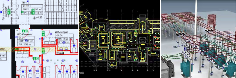
A wiring diagram shows how the electrical system is physically connected. Unlike a schematic, it displays symbols and connections that represent the actual wiring and component layout. This simplifies wiring diagrams for electricians during installation, maintenance, and repairs. Schematics and wiring diagrams serve different purposes, but both are important parts of a complete electrical design package.
Panel layout drawing: elements, purpose, and red lines
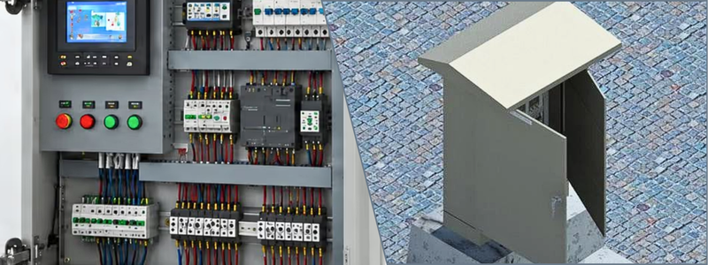
The panel layout drawing services specify the location of all circuit elements within a panelboard enclosure. Individual elements that are depicted in their approximate proportions will be arranged properly to reflect the actual physical layout within the enclosure. The panel layout is used to actually build the panel by mounting the circuit elements within the enclosure, making mechanical clearances and other considerations of a real-life build far more relevant than theoretical circuit function.
RELATED: Benefits of AutoCAD for Electrical Drawings with Freelance Engineering Services & Companies
Thermal dissipation becomes a concern, especially when elements that produce a lot of heat are placed too close together. The same applies to terminal blocks: the wiring diagram specifies the terminals used to make connections, but the panel layout has to have clear access to those terminal blocks so that field electricians can actually make the connections without damaging other circuit elements.
What is a panel schedule?
The panel schedule is a tabular list that provides details about every circuit served by the panel. This is the information an electrician or facilities manager needs to identify the circuit. It allows an electrician to identify a particular load without opening the panel door and reading the schematic. The panel schedule is usually attached to the panel door. It provides an invaluable reference for an electrician. It specifies the circuit number and description, the circuit breaker size and wire gauge, and what load the circuit is actually powering.
Why is maintaining the panel schedule important?
A panel schedule is an essential component for any panelboard because it supplies power to multiple circuits downstream. This is the case for most electrical distribution boards. An electrician should not attempt to open a panel door without first consulting the panel schedule, as it is too easy to mislabel a circuit breaker. Electricians and inspectors alike tend to rely on a panel schedule even if it was prepared several years ago. Maintaining this document becomes a big responsibility.
RELATED: Understanding CAD Services: From 2D Drafting to 3D Conversions
What is a single-line diagram?
The single-line diagram (also often referred to as the one-line diagram) represents the electrical distribution system as a whole. Whether real or not, the diagram uses a single line to represent each circuit. It focuses on providing an overview of the main elements of the system. A single-line diagram, even so, specifies the details of the system’s distribution architecture. It includes the ampacity of the main service, distribution of panels, and the transformers. It also includes the ratings of all circuit breakers and the short-circuit current ratings (SCCR) of all elements.
How are single line diagrams used for industrial control panels?
Industrial control panels usually only have one or two control circuits, but the same principles apply: a single-line diagram for an industrial control panel usually only depicts the control circuit, specifying the circuit breaker, feeder circuit ampacity, disconnect switch, and control transformer. The single-line diagram nevertheless serves the same function as the expanded diagram. It provides an overview of the control system needed to power a specific machine.
What should be included in a control-panel drawing set?
A properly prepared control panel drawing set should provide information necessary to understand, assemble, and troubleshoot the panel. It usually contains a power schematic, control schematic, wiring diagram services, PLC I/O list, and the bill of materials. These five types of drawings are crucial for electricians, engineers, and panel builders because each of them contains particular information concerning the control panel.
What is a power schematic?
A power schematic shows the main electrical power circuit. It also identifies important information such as voltage ratings and circuit protection components. It also provides a clear overview of how power enters the panel and reaches the equipment being controlled to show that it is flowing properly.
What is a control schematic?
The control schematic is often called a ladder diagram. It focuses on the control circuit that is lower in voltage. It typically shows the circuits when it starts, stops, or interlocks with larger power circuits. It is usually operated by motor starters or drives. This allows electricians and engineers to understand how the control logic interacts with the panel’s power components so that they won’t have a hard time.
How are PLC I/O and components documented?
PLC inputs and outputs should be clearly identified and cross-referenced to the appropriate parts of the schematic. This will indicate to the panel builder what signals should be connected to the PLC. Contains the reference designations for identifying them on the drawings.
The freelance BOM designers become particularly important when building control panels to UL 508A requirements. This is because it identifies the components that need to be evaluated for electrical safety compliance. For reference, designations commonly follow conventions recommended by the Joint Industrial Council (JIC). This is to give them broad recognition across the industry.
Which electrical standards apply to control panels?
Drawings in a control panel need to account for the standards that apply to the project and its location. In the US, the National Electrical Code, or NEC, is published as NFPA 70. It focuses specifically on the electrical equipment and systems used with industrial machinery.
It actually specifies requirements like electrical clearances, enclosure types, and the aptness of circuit components. Therefore, the UL 508A listed panels have been subjected to the appropriate safety evaluation and can recognize components that are designed to be installed within a listed control panel. What usually addresses panel construction and electrical safety for industrial control panels is UL 508A.
RELATED: Benefits of Prototyping for Electronics Engineering Design for Improving New PCB Hardware
What is electric safety and international standards?
Not all electrical standards deal directly with the construction of panels. For instance, NFPA 70E is about electrical safety practices when working on or near energized equipment. So, in some cases, warning labels for hazards like arc flash may require specification for drawings on a control panel.
So, these standards also vary based on the installation site. CSA C22.2 No. 286 applies to industrial control panels only, and the Canadian Electrical Code applies to electrical installations. The IEC 61439 series and IEC 60204-1, respectively, contain standards for low-voltage assemblies and the electrical equipment of machinery, respectively, for international projects. Knowing these requirements can help prepare control panel drawings that are suitable for the equipment and its target market.
Electrical drawing types at a glance
| Drawing Type | Shows | Primary User |
| Schematic / ladder diagram | Circuit function and logic, standardized symbols | Design engineers, troubleshooters |
| Wiring / connection diagram | Physical layout and actual wire routing | Field electricians, installers |
| Panel layout | Physical component placement inside the enclosure | Panel builders, fabricators |
| Panel schedule | Circuit number, breaker size, wire gauge, load | Electricians, facilities teams |
| Single-line diagram | Full system overview, one line per circuit | Inspectors, utilities, engineers |
| Control-panel drawing set | Power schematic, control schematic, wiring diagram, BOM | Panel builders, maintenance techs |
Need a full drawing package built to NEC, NFPA 79, or UL 508A conventions? Cad Crowd’s freelance network includes electrical drafters experienced in building and industrial control panel documentation. Browse Cad Crowd’s CAD services to scope your next electrical drawing package.
RELATED: Best 50 Platforms to Hire PCB Designers and Freelance Electronics Engineers for Startups
What is electrical drafting software?
The selection of the proper electrical CAD software services can determine an effective and efficient design and documentation of a project. Whether creating electrical systems, control panels, or complicated wiring harnesses, each platform offers a different workflow. Some are also built specifically to be used with mechanical CAD to facilitate coordination between electrical and mechanical teams.
AutoCAD electrical
AutoCAD Electrical is the extension of AutoCAD to the electrical industry, using industry-specific libraries & tools. So, it has the same interface and file formats as other AutoCAD products. This makes it a convenient option for companies that are already using AutoCAD for mechanical engineering services. Particularly so when both have to operate within the same project environment.
EPLAN
EPLAN is a popular electrical design platform in Europe and is becoming more popular among North American control panel builders. It has a number of great features, one of the best of which is that it is based on a database. So, if a drafter edits one document, the other documents and drawings could possibly be updated automatically. Bills of materials, schematics, and panel layouts can be interconnected. It then minimizes the chances of making mistakes in documentation and unnecessary effort.
SOLIDWORKS electrical
This is tightly coupled with SOLIDWORKS mechanical CAD software. This is especially helpful for projects requiring precise placement of electrical and mechanical components that are hard to work with. With the electrical schematic, for instance, in a detailed mechanical design of an electrical harness or a control panel, the 3D CAD data can be synced with the schematic. So, this helps to detect possible mechanical interaction problems without producing the actual prototype.
Zuken E3.series
Zuken E3.series is used for electrical design and documentation services, especially in the automotive and aerospace industry. The software emphasizes wiring harness design and can handle information from wiring harnesses to panel layouts. It has a large library of wires and cables that are helpful for larger harness projects; thus, it is quite appropriate for complex projects like those in the manufacturing of commercial vehicles.
What is the difference between electrical drafting and PCB layout?
The principles of electrical drafting also apply to product electronics and PCB design services, but they use different tools and applications. Schematic capture is kind of similar to an electrical schematic in PCB development. This is usually where it is used to show the connections between the parts. Another way of saying this is that PCB layout is the process of positioning those components on the circuit board, similar to how a panel layout positions components on a panel.
RELATED: Top 7 Reasons to Outsource Engineering Design Activities at Your Company for Efficiency
Where does wiring harness design fit in?
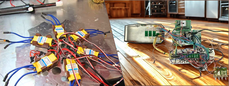
Wiring harness design ties these two together because it is required in both documents. It defines the electrical connections and determines the physical layout. A control panel schematic illustrates the connections between the circuit elements, and a harness design provides a record of the wires, cables, connectors, etc. used to carry the connections. In the case of connected products and smart devices, designers might have to use both a PCB design and wiring harness software packages, as the end product might include both a circuit board and external wiring.
It can be easier to navigate the electrical design workflow when you understand how the various areas fit into one another. To give you some background, Cad Crowd’s engineering drawing guide tells you about the similarities and differences between engineering drawings and schematics, and Cad Crowd’s guide to IoT and wearable design offers more details on PCB design for connected products.
If your product needs both a custom housing and the electronics inside it, Cad Crowd’s product design services cover that combined scope, and it’s worth reviewing Cad Crowd’s guide to injection molding design costs if the enclosure will be molded.
RELATED: How the Engineering Design Process Helps You Craft New Products for Consumer Goods Firms
Download: electrical drawing package checklist
We built a one-page checklist covering what belongs in a complete electrical drawing package, from schematic through panel schedule to bill of materials. It’s free to download, ungated, and includes a direct link to request a quote from a Cad Crowd electrical drafter.
Conclusion
Electrical drafting isn’t one drawing; it’s a coordinated set that serves designers, builders, and inspectors differently. Getting the schematic, wiring diagram, panel schedule, and single-line diagram right protects a project from installation errors and failed inspections. If your project needs a complete electrical drawing package, browse Cad Crowd to hire a freelance electrical drafter experienced in NEC, NFPA 79, and UL 508A documentation. If your project needs a complete, accurate electrical drawing package, browse Cad Crowd to connect with a freelance electrical drafter experienced in NEC, NFPA 79, and UL 508A documentation.
How Cad Crowd can help
Cad Crowd connects businesses, engineers, contractors, and manufacturers with experienced electrical drafters who can prepare accurate and organized electrical drawing packages. These professionals can create schematics, wiring diagrams, panel layouts, panel schedules, single-line diagrams, control-panel drawings, PLC documentation, and bills of materials based on your project requirements. Whether you need documentation for an industrial control panel, electrical installation, wiring harness, or product electronics, Cad Crowd can help you find a qualified specialist familiar with the appropriate drafting standards and software. Browse Cad Crowd’s electrical drafting services today and request a free quote for your project.