Help! How to create a parametric model of this transmission bellhousing

3 Replies | 516 Views
karthikb1
0
Hi all, I have received a bellhousing non-parametric CAD model from Grabcad. I am interested in converting it to parametric model. But its geometry is very complex and i cant able to get an idea, in how to identify the basic geometries required to start constructing the model.

Tejjy Inc.
0
I totally understand your situation — reverse-engineering a complex bellhousing like this can feel overwhelming at first! The good news is that it’s absolutely doable if you break it down step by step.

Here are a few tips to help you get started:

✅ 1. Identify the main features first:
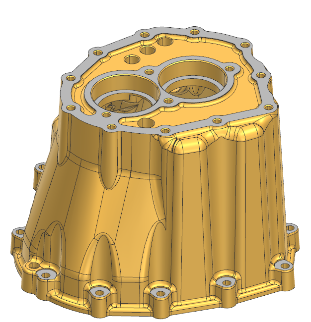
Look for the biggest and simplest shapes that define the part — for a bellhousing, this is usually the main cylindrical section, the flange, and the bolt hole pattern. Start with these as your base sketches.

✅ 2. Work from simple to complex:
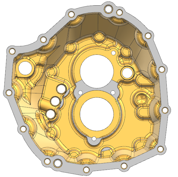
Once you have the main cylinder and flange, add the larger holes and bosses. Then, move on to the smaller details like fillets, ribs, pockets, and additional holes.

✅ 3. Use reference planes and symmetry:
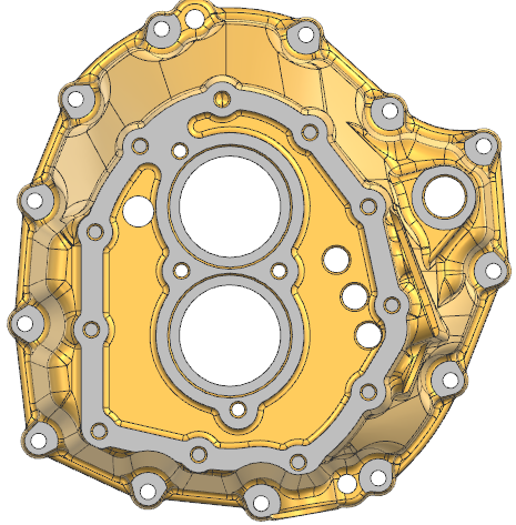
Most bellhousings are symmetrical. Use planes and mirror features to save time and keep things parametric.

✅ 4. Import the mesh or surface as reference:
Bring the non-parametric model into your CAD as a reference body. Use it to trace sketches and measure dimensions directly — this will help you match the curves and contours more accurately.

✅ 5. Take it step by step:
Don’t try to rebuild everything in one go. Create a rough version first and refine the details as you go.

If you’re comfortable, you can share which CAD software you’re using — I or someone else here can probably give more specific workflow tips for that tool.

Good luck! This is great practice for learning how complex cast parts are designed.
karthikb1
0
Thanks for your detailed inputs, I will try and post here. I am using Siemens NX.
Tejjy Inc.
0
karthikb1 wrote:.You’re welcome — glad it helped!

Since you’re using Siemens NX, you’re actually in a great position because NX has strong tools for reverse engineering. Here are a couple of extra tips for NX specifically:
Use the ‘Wave Geometry Linker’ - You can link geometry from your reference mesh or solid into your new parametric model. This makes it easier to build sketches that match the original shape.
Try the ‘Section’ tool - Create section curves through the mesh at key areas — like flanges, bolt circles, and ribs. These sections help you build accurate sketches.
Organize with Datum Planes - Set up multiple datum planes along the length and critical features — this makes sketching and extruding much more manageable.
Leverage Synchronous Modeling (if needed) - NX’s Synchronous Modeling can help tweak or adjust non-parametric geometry when needed — handy if you want to clean up the reference shape before recreating it.


In order to post an answer, you need to .