Ceiling mounted antenna Blind
in
Industrial Design Services
held by
TD
Last seen:
Contest Ended, Winner(s) have been selected.
-
Open
-
Choosing Finalist
-
Ended
Description:
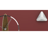
Hi, thanks for reading. We are looking to design a very simple, yet elegant plastic to house a small circuit board and antenna. it will need to mount to a ceiling tile, ceiling grid or with screws through some sort of mounting plate. (should have a magnet option) there should be a set screw or other mechanical method to connect from the antenna to the base. it's very likely this will be mounted nearby to one of these access points,www.arubanetworks.com/products/networking/access-points/550-series/ but we don't want to copy it, just be aesthetically pleasing and compatible. The PCB will be 2" round circle and I have 2 options for an antenna perpendicular to the PCB, first is 2-3/4 inches the second is 1 inch. the antenna will hang DOWN towards the floor from the PCB which shall be parallel to the ceiling. if the design appears much more pleasing with the shorter option that is preferred. I would guess 3" in diameter would be maximum. there will be a small USB cable exiting the side of the device, it would be nice if this had some sort of channel that held the cable in place in the event of accidental pull (strain relief idea) but mainly just so it didn't get unplugged by someone pulling on it. a 180 degree gentle radius on the channel may accomplish this? an s curve? the cable will be micro USB on one end into the PCB and regular USB on the other. the files received at the end of the project should be in a format easily viewed by our team without special software but should also be ready for the plastics tool maker to create the tool.
Wants:
we will evaluate this on simplicity of tooling and assembly as well as aesthetics. the design should be elegant in its simplicity.
Don't Wants:
i don't want anything that looks like half a ball glued to the ceiling. not a copy of the access points.
Ask for Sample:
we will 3d print samples in our office. please provide 3d printer compatible files.
 Prepaid Prize
Entries
1st Winner
#25 Ceiling mounted antenna
by Quantum_Designs

#19 Ceiling mounted antenna v3 -Support files
by Rishi reddy

#2 Ceiling mounted antenna ver01
by Insan Gunawan

#17 Ceiling mounted antenna v3
by Rishi reddy

#13 Ceiling mounted antenna
by Saurabhverma

#12 Ceiling mounted antenna
by Quantum_Designs

#10 Ceiling mounted antenna v2
by Rishi reddy

#6 Trovex - Concept 1 v1
by ZM Designs

#1 Concept Design
by Jinen Sheth

Download Files
#7 Ceiling And Table Mounted Antenna
by Chaniago

#11 Ceiling mounted antenna
by Saurabhverma

#15 Angular Antenna Housing
by Akash Jayanthan


#5 The box of electronic device
by Ecco

Download Files
#4 CEILING MOUNTED ANTENNA
by benjamino

Download Files
#18 Ceiling mounted antenna
by sherifelsheikh

#3 Mount
by benjamino

Download Files
- SolidWorks 2018 — Plastic
- SolidWorks 2018 — P0
- SolidWorks — Antenna connect
- SolidWorks — Antenna connect
- SolidWorks — Ceiling board
- SolidWorks — Plastic
- SolidWorks 2018 — Plastic
- SolidWorks 2018 — P0
- SolidWorks 2018 — Mount
- SolidWorks 2018 — Antenna
- SolidWorks 2018 — Antenna
- SolidWorks 2018 — Fastener
- SolidWorks 2018 — Fastener
#24 Ceiling mounted antenn
by Infinite 7_∞ Designs

#29 Ceiling mounted antenna
by sherifelsheikh

#28 Turtle
by andyt

Download Files
#27 Ceiling And Table Mounted Antenna R-1
by Chaniago

Download Files
- 3D PDF Files 2020 — Ceiling Mounted Table Antenna
- AutoCAD Mechanical 2020 — 3D Ceiling Mounted Antena
- AutoCAD Mechanical 2020 — 3D Table Stand Antena
- STEP/STP 3D Modeling 2020 — 3D Ceiling Mounted Antena
- Rendering Images 2020 — Bracket
- Rendering Images 2020 — Assembly Part
- Rendering Images 2020 — Table Antenna
#26 Concept 1
by studio701

Download Files
#30 Ceiling mounted antenna v3 - IM
by Rishi reddy

Download Files
- SolidWorks 2018 — Base plate V3
- SolidWorks 2018 — Base V3- IM
- SolidWorks 2018 — cover v3 - IM
- SolidWorks 2018 — assembly V3
- image — rectified cover draft analysis 1
- image — half cover v3
- SolidWorks 2018 — half cover v3 -IM
- image — 220px-Cantilever Snap-fit
- image — New Fits V3
- image — New Routing V3
- image — New Base Plate Fit
- image — V3 IM sectional view
#23 Design
by Shreyasp


#21 User centered antenna ball
by Saurabhverma

#20 ceiling_mount_7.stp
by hannahdesigns

Download Files
#16 angular antenna housing
by Akash Jayanthan

Download Files
#14 concept7cma
by hannahdesigns

Download Files
#9 Ceiling mounted antenna v1
by Rishi reddy

Download Files
- SolidWorks 2018 — Base plate
- SolidWorks 2018 — Base
- SolidWorks 2018 — PCB
- SolidWorks 2018 — Cover 1
- SolidWorks 2018 — ceiling mounted antenna
- SolidWorks 2018 — ceiling mounted antenna-exp
- SolidWorks 2018 — snap fit -base base plate
- SolidWorks 2018 — snap fit -cover base
- SolidWorks 2018 — ceiling mounted setup
- SolidWorks 2018 — Desk setup
Discussion
Showing last 20 comments - View All
Thanks for the opportunity. But I have a slight suggestion for future competitions. You could attach maybe hand drawing/example photo for what design you require, because your description of this product based on just wording was honestly quite vague. I'm saying this as you can receive many more designs that can be worthwhile.

Thanks for opportunity

This contest is now closed, thank you to everyone for all the excellent submissions. the team will be reviewing today and it's likely we will choose the winner tomorrow.
thank you again, you are all very talented.
thank you again, you are all very talented.

 , Hello Mr. TD, thank you for the ratings, Please check attached 2nd concept :)

Thank you for the coontest TD. I have attached all the 3d printable files for all the concepts, If you face any difficulty in printing the files, I am available to make iterations based on your printer type, nozzle size, extruder size.
Feel free to contact anytime to discuss changes and iterations for any design concept :)
Feel free to contact anytime to discuss changes and iterations for any design concept :)

Thank you for the opportunity TD. I'll be online and available if at all you'd like to discuss/suggest changes to the model that'll make or break the decision as a part of your team review.
Thank you everyone for the submissions and comments. We will be doing a team review later today and will respond with ratings and comments. Thank you!
 , Hello Mr. TD, If you give some ratings and OR feedback, it will be helpful for us to improve our designs :)
Hey TD,
Just an additional detail to my description :
The designi submitted is 2.4 inches wide and 1.4 inches tall
Just an additional detail to my description :
The designi submitted is 2.4 inches wide and 1.4 inches tall

Hey CH, could you please explain the position of the USB port relative to the PCB, will it be parallel or perpendicular to the PCB.
Also what side will the cable be connected from- front, back or side.
The previous comments have left me a bit confused. If possible a hand drawn sketch explaining this would be greatly appreciated.
Thanks
Also what side will the cable be connected from- front, back or side.
The previous comments have left me a bit confused. If possible a hand drawn sketch explaining this would be greatly appreciated.
Thanks

Hi...
how much is the total weight of the antenna?
Regards
Chaniago
how much is the total weight of the antenna?
Regards
Chaniago
The thickness of the PCB is 1.5mm.
The antenna will be a helical antenna or coiled wire standing off the PCB.
Similar to this one (but will be perpendicular)
https://www.enocean.com/typo3temp/GB/csm_STM320_Sensor_f_Mag_cmyk-300dpi-wht_exemplary_image_b5096fd1c0_2f25297f95.jpg
The antenna will be a helical antenna or coiled wire standing off the PCB.
Similar to this one (but will be perpendicular)
https://www.enocean.com/typo3temp/GB/csm_STM320_Sensor_f_Mag_cmyk-300dpi-wht_exemplary_image_b5096fd1c0_2f25297f95.jpg

Hi,
second question what is the intended thickness of the pcb
- Joel B
second question what is the intended thickness of the pcb
- Joel B
Hi,
Could i get more detailed dimensions of the antenna?
-Joel B
Could i get more detailed dimensions of the antenna?
-Joel B
The link to the access point is only for a design reference. You will not be designing an access point. The design is for an accessory to the access point. Since they will be mounted near each other it would be nice to have similar aesthetics.

We got to design the access point, with reference to the link, along with the antenna assembly?
Hi, I'll address several comments here:
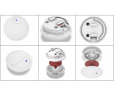
we would prefer a snap-together assembly. (base plate to housing) the PCB can snap into place as well... if a screw pattern is used it should be 2 screws at opposite sides of the PCB and use plastic stands to hold it up on the opposite sides
the material has not been chosen yet,
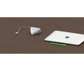
The micro USB should be connected underneath/hidden but if removed from the base the cable can be easily removed/changed to a new one. there should be 2 cable routing options, one directly out the base (going into the ceiling) and the other out a little u shaped space in the side. pinched kind of between the baseplate and the housing.
the device can be mounted on the wall if needed. since the antenna is internal it will stay in the same orientation. perpindicular to the PCB and standing up 1 inch or 2-3/4 inches depending on the design. (but UNDER the plastic housing, internal)
I may choose a second design for award if we find 2 that are close to meeting our needs.
if the ceiling is not accessible the cable will come out the side, mounting over not accessible place will not be an option.
thank you!
we would prefer a snap-together assembly. (base plate to housing) the PCB can snap into place as well... if a screw pattern is used it should be 2 screws at opposite sides of the PCB and use plastic stands to hold it up on the opposite sides
the material has not been chosen yet,
The micro USB should be connected underneath/hidden but if removed from the base the cable can be easily removed/changed to a new one. there should be 2 cable routing options, one directly out the base (going into the ceiling) and the other out a little u shaped space in the side. pinched kind of between the baseplate and the housing.
the device can be mounted on the wall if needed. since the antenna is internal it will stay in the same orientation. perpindicular to the PCB and standing up 1 inch or 2-3/4 inches depending on the design. (but UNDER the plastic housing, internal)
I may choose a second design for award if we find 2 that are close to meeting our needs.
if the ceiling is not accessible the cable will come out the side, mounting over not accessible place will not be an option.
thank you!

The micro USB should be easy connected/disconnected from the outside of housing?
I'd like to know the material that will be used for injection if it is already chosen, in case of series production.
I'd like to know the material that will be used for injection if it is already chosen, in case of series production.

Hi TD.
I just done my preliminary design before you add aditional term from your managers.
Please review. I'll make update it later to meet the latest requirement.
Btw, just a question, maybe...Is there any additional winner's prize? (or for 2nd, 3rd winner) since addtinional requirement added to the contest :) 😃
Cheers,
Insan

Hello TD! Thank you for your design brief. some questions:
Is the power coming in from the USB? Are there any buttons on the device, status LEDs, reset holes? Are there any Logo considerations? What about heat dissipation vents? Is the antenna inbuilt on the PCB or a screw type antenna.
Can the device mounted on the wall? If the device is mounted in the wall the antenna will be sideways?
How is the USB routed within the ceiling if the ceiling is already finished or that is not an option ?(just curious)
Thank you!
Similar Contests on Cad Crowd
Design a vortex tube
The project consists of designing a 3D model, a simulation and a drawing of Ranque-Hilch vortex tube.
This product is supposed to create a cold fraction and a hot fraction from 6-7 bar compressed air, the cold fraction is a temperature drop of 40°C.
The material of the tube is aluminum, we are willing to manufacture it on cnc lathe, so consider fabrication requirements and optimal material use.
Men's Wristwatch
The design submission should include:
Rendered Imagery: showing front, back, top, bottom left and right, and 3/4 perspective views. Rendered views for the front, back, top and bottom can be combined into one or two image files if appropriate. The perspective view must be a separate image.
It is encouraged that the rendered images be as realistic as possible and provide enough lighting to show design details. Environment and lighting style is left to the designer.
Requirements:
1. Men’s wristwatch.
2. It should have an outdoors and sporty look. An ideal buyer would be someone in the armed forces.
3. Illumination around the watch ring and on the hours seconds and minutes hand using tritium tubes.
4. The closest competition brand would be Luminox.
Modern wooden Arabic Incense burner (Mabkhara)
Hello Designers,
Mabkhara (incense burner) is a well know product used in the Arabic region to burn agarwood using hot Charcoal. More information on Mabkhara and how its used please see this video or other similar videos.
https://www.youtube.com/watch?v=1IEVaVIg60k
Traditionally is was made from wood with copper nails as decoration or in some regions and completely from copper in other regions.
we are looking to modernize the wooden Mabkhara shape but using the same materials. This is a video on how its made (sorry its in Arabic, but the process and the materials is clear)
https://www.youtube.com/watch?v=hUqho7Wtv0o
Important information:
1- charcoal temperature is around 350 - 420 C (depending on charcoal size), so placing charcoal directly on the wood will burn the Mabkhara. There should be a separating material such as Aluminum to isolate the hot charcoal from the wood as to cover the charcoal hole.
2- Hot charcoal needs oxygen to keep burning, so the charcoal needs air flow and can't be hidden.
3- the Mabkhara is held by hand, so the shape should support that.
Thank you and be creative.
Alki Footwear
I have a patent pending flip flop called Alki Footwear. I have been struggling with some of the connection logistics. I currently have a prototype that features a stub made of EVA/outer sole that has been redesigned in order to offer a secure connection for the foot strap to connect to. I'm looking for a connection design from the stub to the (replaceable) foot strap that can be easily implemented from a manufacturing aspect, great aesthetics, cool factor, and engineered to last and function properly. On the inside of the stubs, my thought is to potentially utilize Velcro as backup connection but not required. I am attaching several photos of my prototype along with an existing product for inspiration only (Bedrock).
Medicine Ball
We are looking for design concepts for a PVC/Rubber medicine ball design. I have included a file showing some of the products on the market. We do not want to copy the designs but want something unique and attractive for a commercial gym application.
We desire the ball have a texture on the surface to aid in gripping the ball when it is thrown.
Color scheme desired is gray and orange but we are open to other ideas if you think it is very attractive.
The ball diameter needs to be 14 inches in diameter.
A logo needs to be on the product and also the weight of the ball in pounds.
Akash Jayanthan
Designer