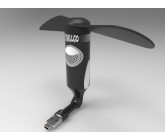
USB/Cell Phone Mini Fan
in
CAD Design
held by
tntgoodies
Last seen:
Contest Ended, Winner(s) have been selected.
-
Open
-
Choosing Finalist
-
Ended
Description:
Good Day,I want to design an upgraded version of this fan please keep in mind its a usb stick and has android phone piece 2 in 1 feature .
Wants:
On/Off Switch, speaker will be inside its stand with bluetooth feature so show a speaker design where its shown in the picture below I want it in that spot. I read some bad reviews of this first product that it faces the wrong direction when it's plugged into your computer so maybe make the product a half inch to an inch longer where it can twist sideways at the bottom. I would like Chillgo logo on the black circle.
Don't Wants:
For the speaker design I do not want a big black box or circle I want a nice design to show a speaker. For example if you google the LeHe scooter it has a speaker on the scooter I want it look similar to that or if you create your own look.
Ask for Sample:
Sorry don't know the software names but I want the look of it be like picture below.
Software:
- png (format)
 Prepaid Prize
Entries
1st Winner
#3 Cell Phone Fan
by ;lzsvpja-] bja]=

Download Files
2nd Winner
#21 Mini_Fan
by Aniket41

Download Files
3rd Winner
#12 MINI FAN
by 25ART

4th Winner
#15 USB/Cell Phone Mini Fan
by Aminegn

Download Files
#13 MINI FAN
by 25ART

#2 Mini Fan
by kriomant

Download Files
#20 Chillgo Mini Wind Force
by REDA

Download Files
#18 Mini Fan
by kriomant

Download Files
#14 Mini_Fan_1
by Aniket41

Download Files
#1 USB/Cell Phone Mini Fan
by Aminegn

Download Files
#26 mini usb fan
by MR. CAD DESIGNS

#27 Mini Fan USB v3
by Ivan Zerpa

Download Files
#9 CELL PHONE MINI FAN
by 25ART

Download Files
#8 Phone Mini Fan
by 25ART

Download Files
#6 Smartphone FAN
by Alex144

Download Files
#28 Mini fan USb V2
by Ivan Zerpa

Download Files
#29 Mini Fan_design 2
by Aniket41

Download Files
#25 CHILLGO Fan by ZC-Design
by ZC-Design

Download Files
#24 USB Cell Phone Mini Fan
by Ivan Zerpa

Download Files
#23 USB/Cell Phone Mini Fan
by Aminegn

Download Files
#22 USB/Cell Phone Mini Fan
by Aminegn

Download Files
#19 USB/CELL PHONE MINI FAN
by Bodhayan

Download Files
#11 Mini Fan Chillgo
by REDA

Download Files
#10 Mini Fan Chillgo
by REDA

Download Files
#17 Mini Fan
by Norita

Download Files
#16 Computer Fan 1.0
by Norita

Download Files
#5 USB MINI FAN 1
by Irfan

Download Files
#4 USB / CELL PHONE FAN
by SUDHANJALI SHUKL

Download Files
Discussion
Showing last 20 comments - View All
Congratulations to all winners!!

Thanks, 25@rt. Congrats to all the winners, very nice designs guys

Congrats to all winners!!!!!

Congratulations ....Jason, (cad geek)

Thank you all this was a very hard contest. Stay tuned for more.

@ms12shah entry ...what a coincidence..lol....I wish you would have at least chosen some colours by yourself !!!!
...what a coincidence..lol....I wish you would have at least chosen some colours by yourself !!!!
Congrats to all Winners !
Congrats to all Winners !
There are so many great designs I added extra prizes.
11pm Bermuda Time

hi tntgoodies
At what time exactly are you going to close the contest. i have a completed design but right now renderings have not been done and i am away from my system. so if you can say the exact time of closing the contest i can upload my design before it ends
thanks
At what time exactly are you going to close the contest. i have a completed design but right now renderings have not been done and i am away from my system. so if you can say the exact time of closing the contest i can upload my design before it ends
thanks
Thanks ;)
 Hi,
Hi,Your opinion is welcome (I want 6 stars) :)
REDA
Reminder I will be picking a winner tomorrow. There are a lot of great designs this will be a hard contest.
hi tntgoodies ,
Thank you for your rate 4 stars is a lot, I expected 2 stars;) Hihi
Thank you for your rate 4 stars is a lot, I expected 2 stars;) Hihi
hi :) Ok !! you can ending whenever you want :)
You can I will be ending the contest Tuesday.
Hi All ,
Nice contest ... I will like to participate as
I saw your image when I clicked it but you might have to ask Cad Crowd I wouldn't know the answer to that.

Hi
This is Bodhayan. I uploaded (submitted) the image (.png) format. By my image is not displaying. what is the problem ?
This is Bodhayan. I uploaded (submitted) the image (.png) format. By my image is not displaying. what is the problem ?
Similar Contests on Cad Crowd
Wood crate/box
Looking for a technical drawing with specs of a wooden box made from used wood material . Boards and 2x4 and plywood sheets. We have already built a box and pictures, some tech drawings that are done by hand and a material list.
As a bonus if someone can figure out what weight this box would be able to hold inside.
I have attached pictures of the box as well as material sheet and basic tech drawings.
Rotary Filling Machine
I would like to purchase a full CAD of a rotary filling machine of at least 12 nozzles. I need to know if you have experience in the field. I am wondering if you have a ready CAD that will enable us to speed up the process.
Non-Electric Nail File
We are working on developing a nail file. The file will interchangeably use different grits of sandpaper. Attached below is a wood file that will act as a template for your file design. However, there are a few changes that must be made.
1. Our file is going to be single-sided, so the securement method must allow for this. The wood file uses a small wheel that tightens the metal arms to keep the sandpaper in place on both sides of the file, so your design must allow for the sandpaper to be secured at the top and bottom of one side only.
2. Measurements: These measurements can be slightly adjusted to accommodate a good design but it should be close.
File length (Not including handle): 4 in
File Width: 1 in (I want to use 1 inch sandpaper, so the total width with the rounded edges will slightly exceed 1 inch and that is fine).
File Thickness 1 cm (The thickness should be consistent and should not taper thinner at the tip like the attached wood file does)
3. The side edges of the file need to be rounded and slightly raised (.25-.5cm raised). The raised edges will allow the user to hold the file from the sides (similar to how you hold a smartphone) so there needs to be some form of added grip to the rounded side edges of the file. The second picture shows how the file will be held from the side, so the design should incorporate this type of position.
The securement method does not have to mirror the wood file. If you have a better design that will hold the sandpaper very securely but is also easy to use/can tolerate a lot of use, this will give you a huge boost in the rankings.
Design of a Modular Selective Graywater Harvesting & Foundation-Shielded Irrigation Syste
1. Project Purpose (The "Why"):
The objective is to create a standardized Shop Drawing for a sustainable building utility that bridges the gap between residential plumbing and landscape irrigation. The system is designed to capture high-quality graywater (specifically from sinks and showers), filter out contaminants (like soap and foam), and deliver it to a specialized, fully encapsulated planting basin. A core priority of the design is Structural Integrity, ensuring that irrigation water is strictly contained to prevent any seepage into building foundations or basements.
2. System Architecture (The "How"):
The project consists of three integrated stages that must be clearly drafted:
Stage A: Selective Source Collection: A dual-track plumbing layout where graywater from specific fixtures (e.g., 3 Sinks, 3 Showers) is isolated from the blackwater (sewage) line during the construction phase.
Stage B: The Smart Control Hub [SC]: A centralized mechanical/electronic node where water quality is assessed. This hub includes a 3-way diversion valve to either direct clean water to the basin or reject soapy/contaminated water to the main sewage line.
Stage C: The Encapsulated Growth Basin: A 2000mm x 2000mm sub-surface planting zone. It is characterized by a 1000-micron Polyethylene Liner [PL] that provides 360-degree isolation from the surrounding soil. Inside, an Engineered Sponge [ES] medium retains moisture, delivered via a Perforated Injection Pipe [P-INJ].
3. Scope of Work for the Designer:
The designer is required to produce a Typical Installation Detail (Modular Design) that includes:
Plan View: Showing the convergence of graywater lines into the Smart Hub.
Cross-Section Detail: A 1:20 scale vertical section of the basin showing the liner, the sponge layers, and the injection point.
Mechanical Schematic: A detail of the [SC] Hub connections (Inlet, Irrigation Outlet, Overflow/Waste Outlet).
Technical Annotations: Detailed notes on material specifications (Liner thickness, pipe gradients, and scalability).
4. Key Technical Constraints:
Zero Seepage: The design must demonstrate a leak-proof interface where the injection pipe penetrates the Polyethylene Liner.
Scalability: The design logic must be applicable to various building heights and land sizes without changing the core mechanical principles.
Maintenance Access: The [SC] Hub must be positioned for easy sensor calibration and valve maintenance.
3d Design/Renders Aviator Sunglasses
Bone Conduction Sound System Spearkers
Wireless Bluetooth
Phone calls with built in mic
Name Logo is a touchpad control on the right side. With the touchpad you can control your music playlist.
Hidden USB Port
Sunglasses Shape- Aviator Pilot
Unisex
Renders of 3 colors
Aniket41
Designer