plug pendant
in
3D Modeling Design
held by
kane m
Last seen:
Contest Ended, Winner(s) have been selected.
-
Open
-
Choosing Finalist
-
Ended
Description:
Hi I am after a design of a pendant which will be gold and whole design should be raised from the base I have provided a image of a similar outcome of the technique used of raising the border and actual design which I want implemented in the new design The plug on the design should be 3 dimensional on a side perspective with the 3 pins someone how raised and the word "the" should be paved with diamonds small enough to fit 2 rows throughout
Wants:
I'm not sure what this means
Software:
- Rhinoceros (RhinoCAD, Rhino 3D)
 Prepaid Prize
Entries
1st Winner
#9 Plug Pendant 2
by John Paulo

#1 Plug Pendant
by John Paulo

Download Files
#2 Plug pendant 1
by Irfan

Download Files
#3 plug1.0
by roylam

Download Files
#4 plug pendant
by edward m barnes

#5 Plug pendant
by Johan

Download Files
#6 Plug Pendant
by Ephela Design

Download Files
#7 Plug
by Ephela Design

Download Files
#8 Plug_Diamond Pendant
by Ephela Design

Discussion
Sooooooo, 17 days left and a winner has already been chosen? I guess there's no point in putting any more effort into this contest. I've got a pretty cool design, almost finished with it too...oh well ;)

Hi good job on the pendant one last thing is to make it not so wide thanks so you can reduce the inches on the sides width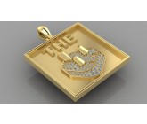

can we submit solidworks file

What are the dimensions to design this for you sir?
4 x 4 inches if not a little more or less depending on design you implamemt

we don't need 3d files. What is the overall size you are looking for ?

instead of images, would you send us 3d file (solidworks file) for this project ?

what size would you like the pendant to be. are you wanting a replica of your attachment or in the spirit of your image attachment?
If so, what is the purpose of the pendant, is it supposed to express love, friendship, status, etc...
Thanks
-Ethan
Mechanical Engineer
Material Science Engineer
Chicago, IL
If so, what is the purpose of the pendant, is it supposed to express love, friendship, status, etc...
Thanks
-Ethan
Mechanical Engineer
Material Science Engineer
Chicago, IL
Similar Contests on Cad Crowd
Wheel Rocker
I want a design for a device that will rotate a wheel about 10 inches in outer diameter about 1 complete rotation back and forth. I prefer for the device to sit on the floor and rotate the wheel back and forth instead of attaching to the carriage frame since I don’t have any carriage specs and they may vary depending on which model is being used The device could attach to the wheel itself, rim or tire. It should be adjustable though to fit on a few different size wheels. It should be designed to be able to adjust to a wheel from 7 - 10 inches.
cordage cam and hook
This is to be a prototype device so it may have a few iterations. There will be additional funds for a planned phase II of this prototype. The idea is a way to secure cordage or twine. The rough specs are 40mm long, 20mm wide and 5mm thick at the base. The cam should be modeled similarly to the look of something you would see on a sailboat. The arch must be just slightly lower than the top of the cam. The cam should be usable for 2mm-6mm cordage.
Powerpac Corporate Offices Design
We are refitting an existing building for our corporate offices.
We are wanting to create a dynamic working environment, as well compelling corporate entrance, we want the design to look modern and also reflect our companies colours as seen on www.powerpac.co.nz
Designer high product
Designing a custom smoke tray with removable parts length 13.0"width 11.0"
Depth 1.25" rounded corners I'm making a medium size tray and large one I also need unlimited corrections
Jewlery Designer for Wedding Ring Design
I am looking for a solid model of an engagement ring. I know what I want, but I need someone to model it for me so it can be cast
BRJackson, P.E.