

3D

PF-26 Pump Adaptor Flange: CNC Part with GD&T Drawing and Fit Calculations (Concept Study)

Concept study (self-initiated, not client work).
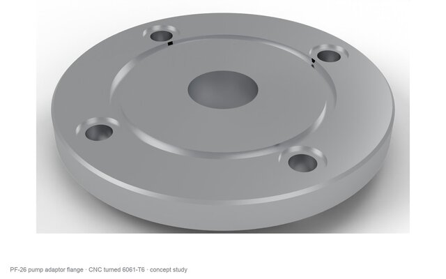
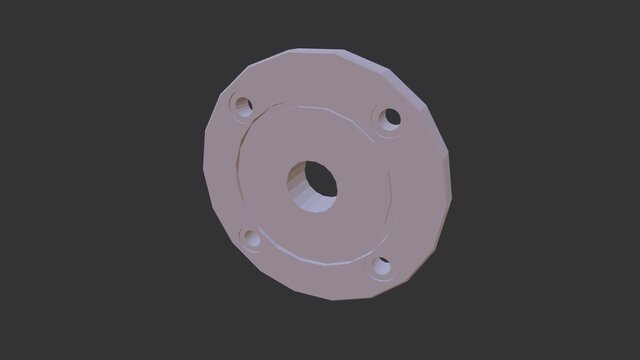
A pump adaptor flange, CNC turned and drilled from 6061-T6, with a GD&T drawing.
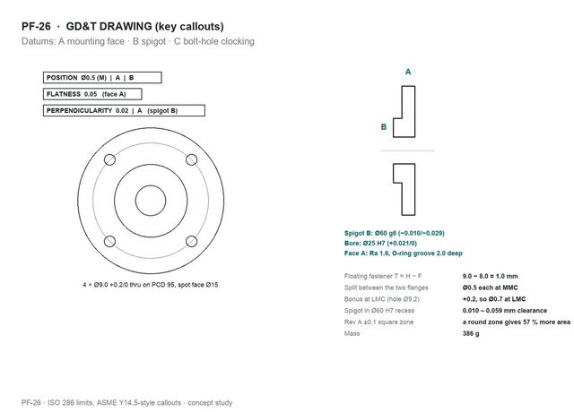
- Datums: A is the mounting face (flatness 0.05), B the Ø60 g6 spigot (perpendicular to A within 0.02), C a bolt hole for clocking.
- Bolt-hole position from the floating-fastener formula: T = H − F = 9.0 − 8.0 = 1.0 mm, split between this flange and its mate, so each gets Ø0.5 at MMC to A|B, with bonus tolerance as the holes grow.
- Rev A used ±0.1 in X and Y. A round zone that just contains that square gives 57 % more area, so the square zone rejects parts that would fit.
- Spigot fit in a Ø60 H7 recess: 0.010–0.059 mm clearance, from the ISO 286 limits.
Deliverables: STEP, GD&T drawing, and renders.
Software: FreeCAD, Python (drawing), Blender.