


3D

3D


NC4touch Behavioral Apparatus

Touchscreen-based behavioral apparatus for flexible, high-throughput cognitive testing with mice and rats.
## Description
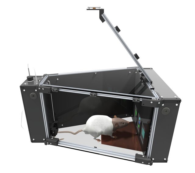
NC4touch is a three-screen, Raspberry Pi-controlled chamber with calibrated liquid-reward delivery, overhead video tracking, sensory cue delivery, and modular device I/O for flexible, high-throughput cognitive testing in mice and rats.
The enclosure consists of a trapezoidal workspace with three touchscreens at the front and a food-reward dispensing system in the rear. The frame uses 10 × 10 mm aluminum T-slot extrusion with SLA-printed brackets and mounts, and laser-cut acetal panels for the enclosure and electronics bays, keeping the electronics fully separated from the behavioral space.
A USB camera mounted above the system captures the full field of view, and removable, laser-cut, 3/16 in clear acrylic lid and floor panels provide visibility and can be easily removed to aid wipe-down cleaning.
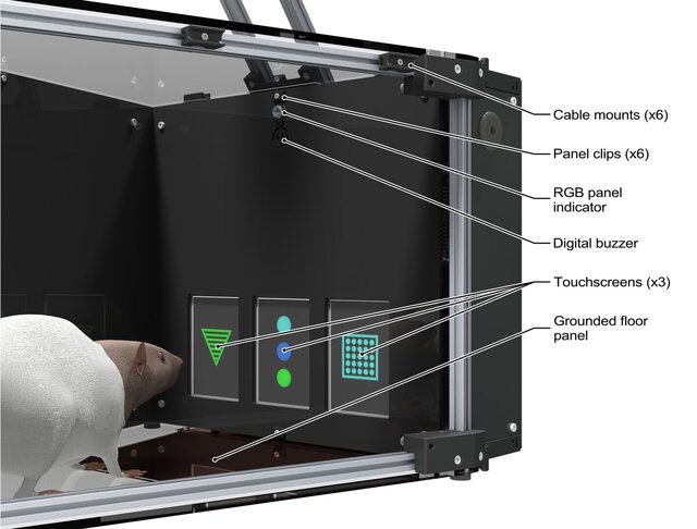
The front panel includes three capacitive touchscreens, each with a cue RGB LED and a buzzer for trial timing and feedback. Each screen is driven by a dedicated FireBeetle 2 M0 microcontroller over a single GDI ribbon cable, with USB used for command and data. Using a dedicated controller per display lets the screens load and render images in parallel, so updates do not block each other and refresh times stay fast under load. Because rodents can behave like a floating ground, a thin copper-foil-laminated floor panel beneath the screens nests into the removable acrylic floor but stays attached to the frame to keep the ground path intact.
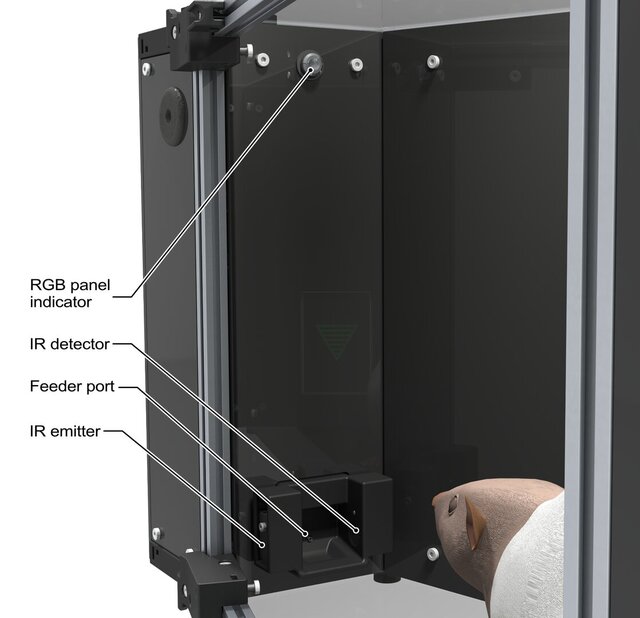
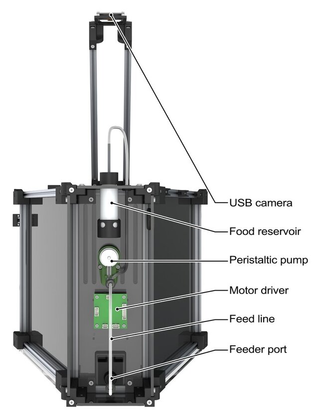
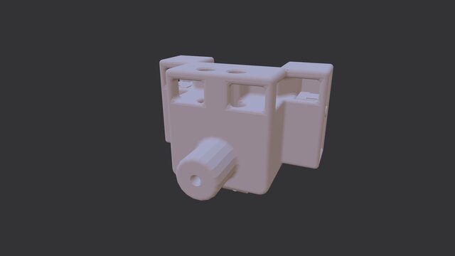
The rear panel integrates a 3D-printed feeder port assembly with IR sensors, a stainless-steel lick spout, and a panel-mount cue RGB LED. A peristaltic pump with a dual-motor controller provides calibrated liquid rewards via food-grade silicone tubing. The IR break-beam detects nose-in and feeder occupancy for precise dosing and event logging. All tubing, port components, and the spout are quick to remove for cleaning, with standard fittings and clear service access.
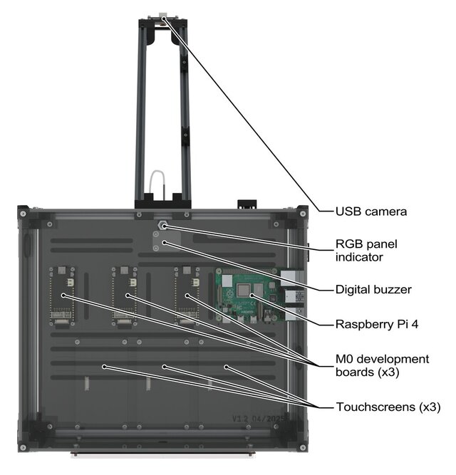
A Raspberry Pi manages task state, device I/O, and logging. The Pi sends image commands to each display module via their microcontroller, controls both cue LEDs and the buzzer, and commands pump dosing. It receives touch events from all three screens and feeder IR signals, and timestamps these alongside the video stream from the overhead camera. Data are written to disk as compact CSV logs plus an optional frame-synchronized MP4 file to support reproducible analysis.
Single- or multi-chamber operation is supported. A single Raspberry Pi can run one or multiple daisy-chained chambers. Multi-chamber setups can be networked over Ethernet with a lightweight browser UI for monitoring and control. Optional PoE provides single-cable power and data to reduce clutter and simplify installation.
Mechanical and electrical design emphasize maintainability and replication. Panels are flat-pattern, laser-cut parts with captive fasteners where appropriate. 3D-printed brackets localize loads and register panel geometry. All external connectors are panel-mount for strain relief and quick replacement. Front and rear electronics bays are isolated from the behavioral space to protect components and simplify wipe-down.
## Role & Contributions
- Co-conceived and architected the system
- Developed all CAD models and assemblies
- Led teams for mechanical build, embedded integration, and validation
- Contributed to control firmware
- Primary hardware maintainer
## Highlights & Key Specs
- **Workspace:** trapezoidal chamber with isolated electronics bays; removable clear acrylic lid and floor for wipe-down cleaning
- **Displays:** three 3.5 in 320 × 480 capacitive touchscreens, each driven by a microcontroller over a GDI ribbon cable, with USB for command and data
- **Control:** Raspberry Pi 4 with PoE; single- or multi-chamber orchestration via browser UI; unified I/O and logging
- **Cue delivery:** RGB indicators on the front and rear interior faces plus a buzzer for behavioral feedback
- **Tracking:** 8 MP USB overhead camera covering the full field of view
- **Reward:** IR break-beam for reward timing and logging, and a quick-service fluid path
- **Data:** CSV logs and optional synchronized MP4 with millisecond event timestamps
## Materials & Fabrication
- **Frame:** miniature T-slotted aluminum extrusion (McMaster 5969N16) with associated T-nuts and fasteners; custom SLA-printed frame-to-panel joining brackets
- **Enclosure and electronics bays:** laser-cut POM-C (acetal) sidewalls and electronics panels; laser-cut clear acrylic top, floor, and grounding panel; SLA-printed brackets for panel registration and service access; SLA-printed clips and cable mounts
- **Displays and controllers:** three capacitive touchscreens (DFRobot Fermion DFR0669) with associated FireBeetle 2 M0 (DFR0652) development board controllers
- **Cue delivery:** four Dialight 8 mm RGB panel indicators (6201121317F) and a Gravity digital buzzer (DFR0032)
- **Camera:** DFRobot 8 MP USB camera (FIT0729) with dedicated SLA-printed camera mount assembly
- **Feeder system:** SLA-printed feeder port assembly; Adafruit IR break-beam sensor (2167); TFS RP-CIII ring pump; stainless-steel tubing, food-grade silicone tubing, and glass vials
## Validation & Performance
- **Bench validation:** end-to-end verification of touch detection, cue LEDs and buzzer, pump dosing, and synchronized video plus CSV logging on single- and multi-chamber setups using the browser UI and PoE
- **Timing and data integrity:** frame-aligned MP4 confirmed millisecond event–video alignment; chambers wrote synchronized session logs to shared storage
- **Networked operation:** multi-chamber control over Ethernet with shared code, firmware, and image directories; no desynchronization observed during concurrent runs
- **Behavioral performance:** all three rats completed an eight-stage visual discrimination task with stage-wise performance gains, meeting the ≥77 percent correct advancement criterion at each stage
## Deployment & Status
- **Development:** completed, Sep 2023–Nov 2024
- **Deployment:**
- NC4 Lab, University of British Columbia (2 studies, 4 rigs)
- Snyder Lab, University of British Columbia (1 study, 2 rigs)
- **Status:** active, Nov 2024–present, NC4 Lab
## Release
- **CAD:**
- Design files including SolidWorks assemblies and parts, cutting templates, and documentation: [https://osf.io/8q9tk](https://osf.io/8q9tk)
- **Software:**
- Firmware and software repo: [https://github.com/NC4Lab/TouchscreenApparatus](https://github.com/NC4Lab/TouchscreenApparatus)
- **On request:** additional design files; assembly notes
## Licensing
- **Hardware:** CERN-OHL-W v2.0
- **Software:** Apache-2.0
- **Documentation:** CC BY 4.0
## References
For additional details, see:
- Modara, G., Lester, A. W., Schwein, I., & Madhav, M. S. (2025). NC4touch: An open-source modular touchscreen apparatus for rodent behavioral testing. bioRxiv. [link pending]
## Included files
*Attached on this page.*
### Image Files
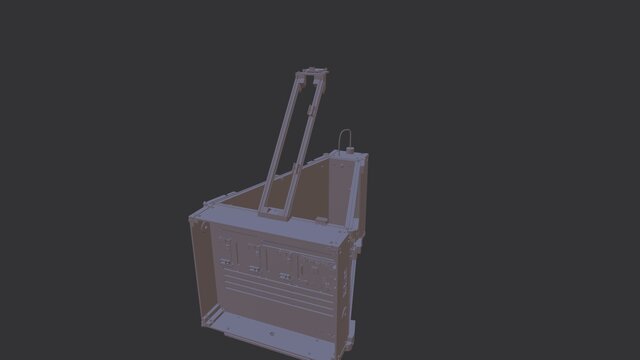
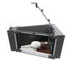
- **render_1.png:** oblique view (right, top) render of full NC4touch behavioral apparatus including exposed interior
- **render_2_annotated.png:** annotated oblique view (front, right) render of interior touchscreen end of apparatus
- **render_3_annotated.png:** annotated front view render of electronics bay on touchscreen side of apparatus
- **render_4_annotated.png:** annotated oblique view (rear, right) render of interior feeder port end of apparatus
- **render_5_annotated.png:** annotated rear view render of electronics bay on feeder port end of apparatus
- **photo_1.png:** bench photo of full NC4touch behavioral apparatus
- **photo_2.png:** bench close-up photo of interior touchscreen end of apparatus
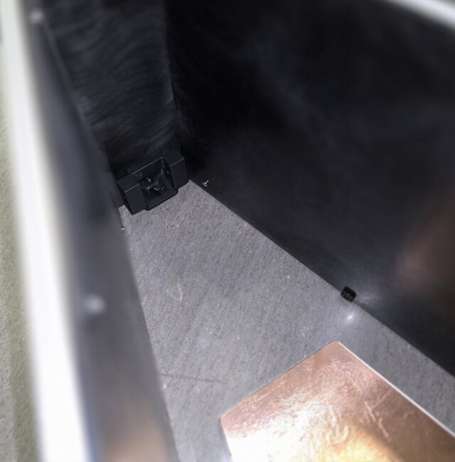
- **photo_3.png:** bench close-up photo of interior feeder port end of apparatus
### 3D Model Files
- **nc4touch_TOP_ASSY.step:** top-level assembly of NC4touch behavioral apparatus with enclosing panels hidden
- **nc4touch_SUB_feeder_port.step:** feeder port subassembly with IR sensors
Files (10)
License:
CC - Attribution
Learn more
Published