


Industrial Automated Heating & Process Control System (5000L Tank)


This project showcases a comprehensive, end-to-end engineering design for an automated industrial water heating system. The objective was to design a system capable of rapidly heating 5,000 liters of RO water from 30°C to 100°C within a strict 10-minute timeframe, utilizing superheated steam.
The scope covers everything from initial thermodynamic calculations and system architecture (P&ID) to mathematical modeling for PID control and full 3D CAD mechanical assembly.
*Key Technical Specifications
-Process Fluid: RO Water
-Volume: 5,000 Liters (5,000 kg)
-Heating Requirement: Delta T = 70°C (30°C -> 100°C) in 10 minutes.
-Calculated Heat Load: ~351,338.4 kCal.
-Heating Medium: Superheated Steam (up to 350°C, Operating pressure: 6-8 bar).
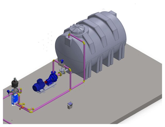
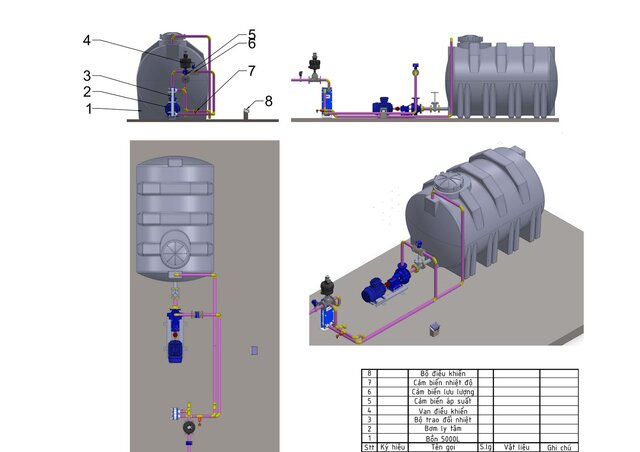
-Main Equipment: Centrifugal Pump (5m^3/h), Plate Heat Exchanger (PHE - Alfa Laval/Danfoss), Pneumatic Control Valve, 5000L Storage Tank.
*System Architecture & Workflow
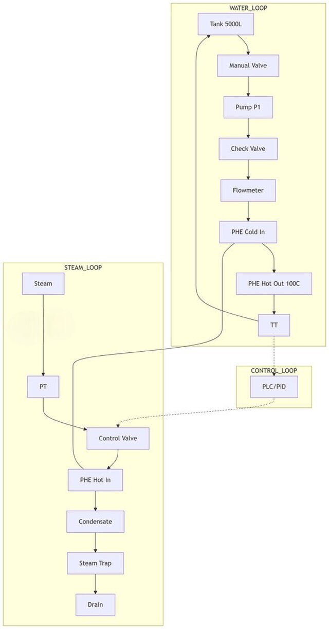
The system is logically divided into three primary loops, ensuring optimal heat transfer and precise temperature control:
1. The Water Loop (Process Variable)
Water is drawn from the bottom of the 5000L tank via a centrifugal pump (5m^3/h). It passes through a flowmeter and enters the cold side of the Plate Heat Exchanger (PHE). Upon exiting the PHE, a PT100 Temperature Transmitter measures the heated water (Target: 100°C) before it recirculates back to the top of the tank.
2. The Steam Loop (Heating Medium)
Superheated steam (up to 350°C) passes through a Y-Strainer and a Pressure Transmitter before reaching the core of the system: the Pneumatic Control Valve. This valve linearly regulates the steam flow (0-100%) into the hot side of the PHE (counter-flow arrangement for maximum efficiency). The condensate exits through a steam trap, preventing energy loss.
3. The Control Loop (Automation)
The system utilizes a closed-loop PID control architecture:
Feedback (PV): The PT100 sensor sends a standard 4-20mA signal representing the current water temperature to the PLC.
Controller: The PLC processes the error using a customized PID algorithm (derived from Laplace transfer functions based on the system's energy balance).
Output (CV): The PLC outputs a 4-20mA signal to the positioner of the Pneumatic Control Valve, precisely adjusting the steam flow to maintain stability and reach the 100°C setpoint within 10 minutes.
Published