

3D

3D

3D

3D

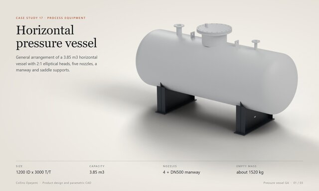
Horizontal Pressure Vessel General Arrangement: Nozzles, Manway and Saddles

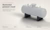
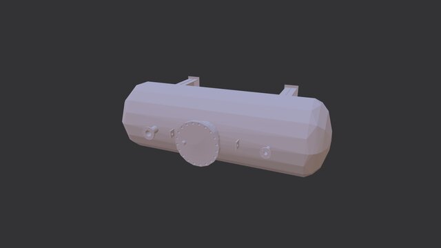
General arrangement model and drawing of a horizontal pressure vessel on saddle supports.
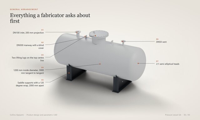
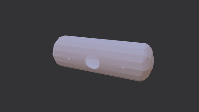
1200 mm inside diameter and 3000 mm tangent to tangent with 2:1 semi-elliptical heads, 3620 mm overall
Capacity 3.85 m3. The volume measured from the 3D model matches the hand formula for the shell plus two heads
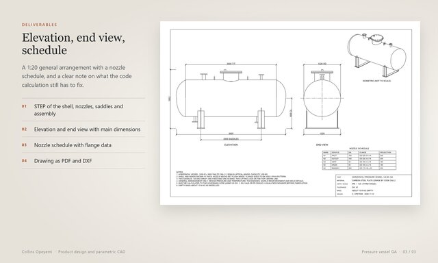
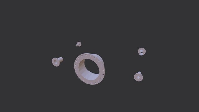
Five connections on a nozzle schedule: DN100 inlet and outlet, DN50 vent and drain, and a DN500 manway with a blind cover. Flanges are drawn to the EN 1092-1 PN16 pattern with the bolt holes modeled
Nozzle necks set into the shell and trimmed flush inside
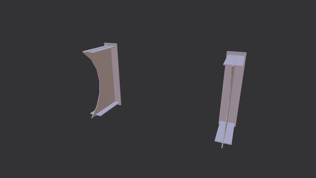
Two saddles with a 120 degree wrap, stiffeners and base plates, and two lifting lugs
About 1520 kg empty, with the shell and heads shown 10 mm thick
Files: STEP of the shell, nozzles, manway cover, saddles and lugs and of the assembly (opens in SolidWorks, Fusion 360, Inventor, Creo and Onshape), a 1:20 general arrangement drawing with a nozzle schedule (PDF and DXF) and presentation renders.
This is a general arrangement, not a code design. Design pressure and temperature, plate thicknesses, nozzle reinforcement and weld details have to be calculated to the governing code (ASME VIII, EN 13445 or PD 5500) by a qualified engineer before fabrication. The model is parametric, so diameter, length, nozzle positions and sizes are quick to change. Message me if you need vessel or tank general arrangements and detail drawings drafted from your data sheets.
Files (9)
License:
CC - Attribution - Non-Commercial
Learn more