

Hexapod Robot - Electronics Selection and Interconnection Design (18 servos)

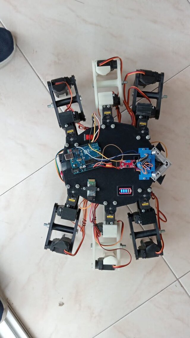
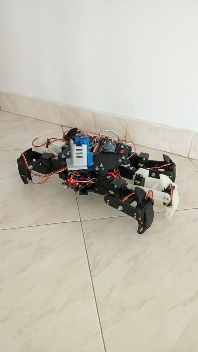
Electronics selection, interconnection design and hardware bring-up for an 18-servo hexapod mapping robot, built as a university robotics project.
MY SCOPE ON THIS PROJECT
I chose the electronic components, designed the wiring of the platform, tested every device individually with the base code that was later folded into the full system, and got the basic walking motion running. The mechanical chassis, the mapping algorithms and the desktop interface were the work of other members of the team. The wiring sheets in this gallery are mine.
THE CONSTRAINT THAT DROVE THE DESIGN
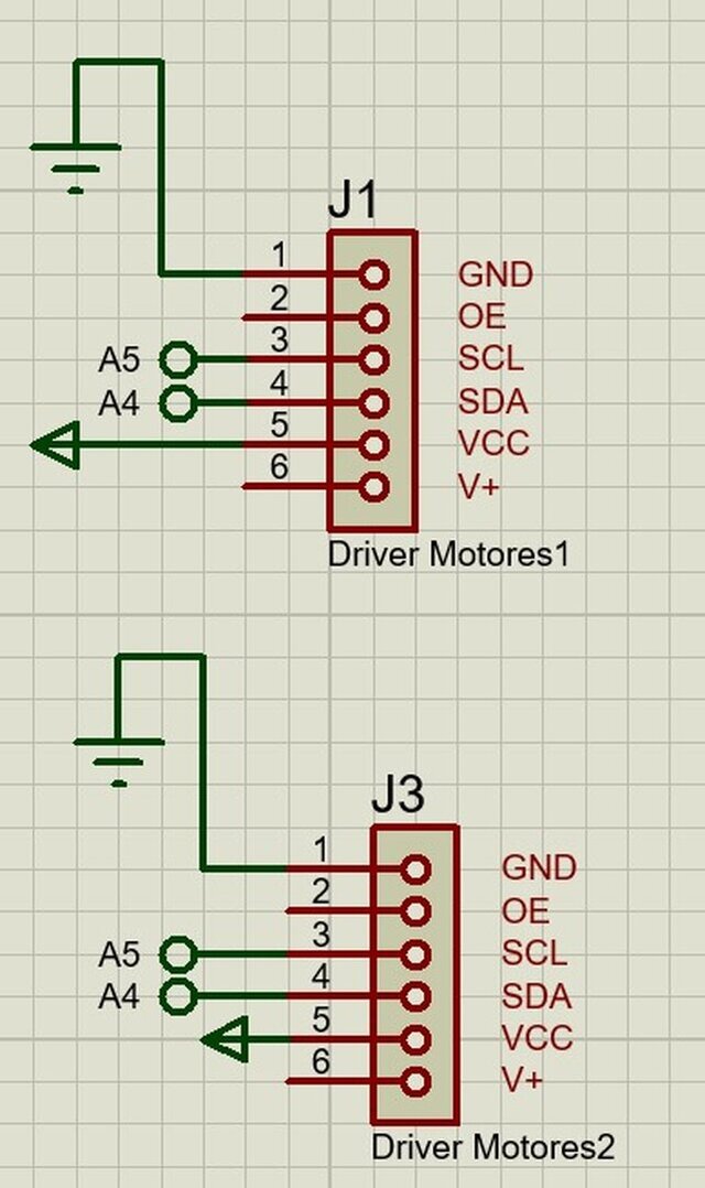
Six legs with three joints each means 18 servos. A single PCA9685 driver handles 16 channels, so the platform needed two of them sharing one I2C bus at different addresses. And at roughly 1 A per servo under load, the supply could not be taken from the controller board: it had to become a separate battery bank sized for the whole set. That came out of measurement during testing, not from an assumption on paper.
WHAT THE SHEETS SHOW
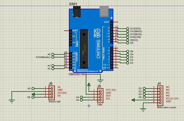
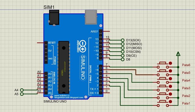
- Robot side: the ATmega328P controller with both PCA9685 servo drivers on I2C (A4/A5), the laser distance sensor on the same bus, a stepper driver for the rotating scanner, a hall sensor used as the rotation home switch, and the radio module on SPI.
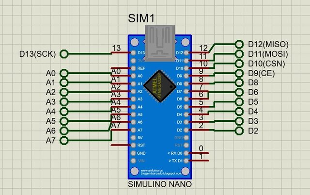
- Handheld controller side: the microcontroller pin map, two analog joysticks with their push switches, two command buttons, a TFT display with series resistors on the control lines, and the matching radio module.
- Six leg limit switches mapped to individual digital inputs.
WHY THE DOCUMENTATION IS THE POINT
A machine with 18 actuators, two buses and a radio link cannot be debugged by tracing wires. Assigning and drawing every connection before assembly is what made it possible to bring up each subsystem on its own and then integrate them, and to find the power problem early instead of during a demonstration. This is the same method I apply to professional hardware work.
Note on scope: this platform used direct point-to-point wiring, not a custom PCB. It is shown here as electronics architecture, integration and test work. For PCB design, see my SwarMind and viscometer entries.
Published