

3D

3D

3D

3D

3D

3D

3D

3D

3D

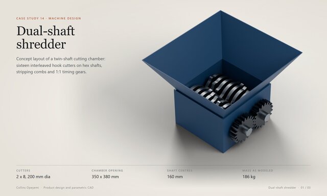
Dual-Shaft Shredder Cutting Chamber: Hook Cutters, Combs and Timing Gears


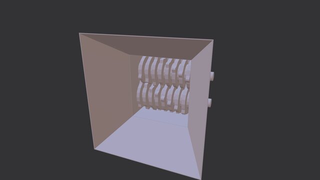
Concept layout of the cutting chamber for a dual-shaft shredder.
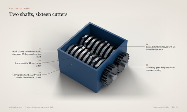
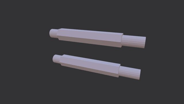
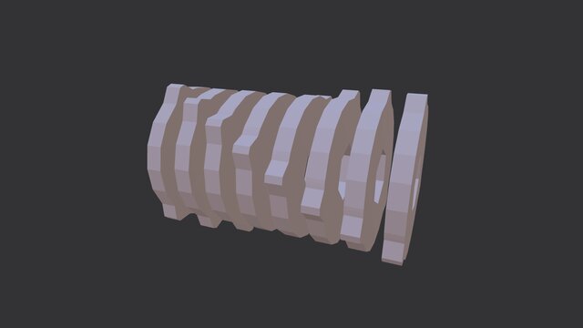
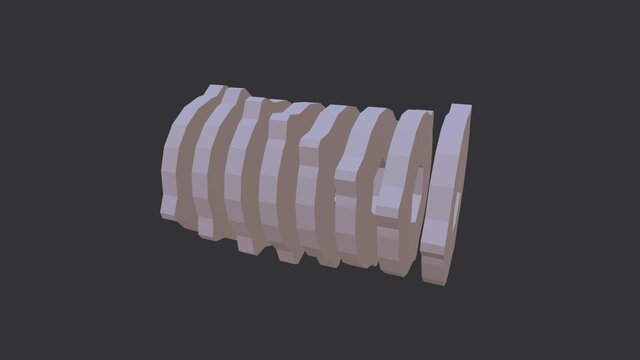
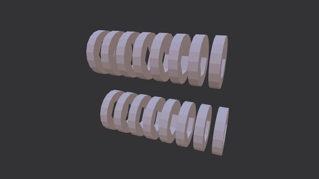
Two counter-rotating hex shafts on 160 mm centres, each carrying eight 200 mm hook cutters, 20 mm thick, with three hooks per cutter
The two cutter sets overlap 40 mm radially and interleave with 0.5 mm side clearance. Each cutter is staggered 15 degrees from the next so the hooks bite in sequence
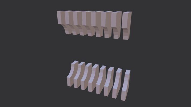
Spacers set a 41 mm cutter pitch, and fixed combs between the cutters strip material off the spacers
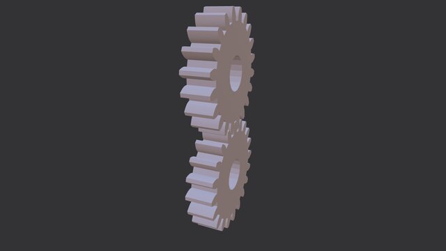
1:1 timing gears (module 8, 20 teeth) with a pitch diameter equal to the shaft centre distance
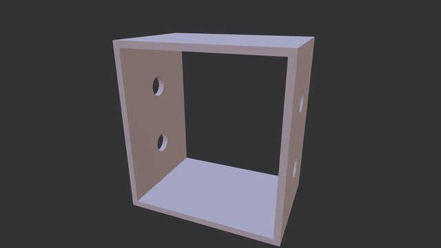
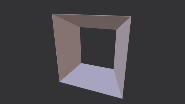
Chamber in 15 mm plate with a 350 x 380 mm opening, flanged bearing housings and a feed hopper
About 186 kg as modeled
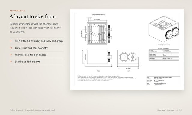
Files: STEP of the full assembly and of each part group: chamber, shafts, both cutter sets, spacers, combs, gears and hopper (opens in SolidWorks, Fusion 360, Inventor, Creo and Onshape), a general arrangement drawing with a chamber data table (PDF and DXF) and presentation renders.
This is a geometric concept, not a finished machine design. The drive, gearbox, stand and guards are not shown, and shaft, bearing and drive sizing have to be calculated for the material and throughput you need. Message me if you need a machine concept modeled, or an existing design turned into 3D and drawings.
Files (14)
License:
CC - Attribution - Non-Commercial
Learn more