Iona Abbey Blind
in
Architectural Design
held by
mtwoed
Last seen:
Contest Ended, Winner(s) have been selected.
-
Open
-
Choosing Finalist
-
Ended
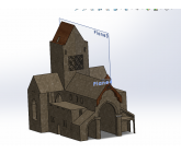
Description:
A recreation of the cathedral section of Iona Abbey in sufficient detail for preliminary thermal, luminance, and acoustic simulations. The model should be furnished, with materials applied in the fashion found in the interior photo below. An example of the interior for reference to materiality can be found at: canmore.org.uk/collection/1268473.
Architectural drawings can be found at: canmore.org.uk/event/546182. Links at the bottom of the page under “Related Collection Item(s)” will provide high resolution, zoomable images to make out details.
Wants:
Submissions will be evaluated on their recreation of the subject and simulation preparedness based on accuracy and amount of detail.
Additional Information
Submissions should be made as OBJ files with material properties attached for Solidworks analysis.
 Prepaid Prize
Entries

Discussion
Submissions should be made as OBJ files with material properties attached for Solidworks analysis.

The final deliverable for the contest are the model files themselves. Snapshots may be used to demonstrate details and accuracy of the submission.

Hi,
You still haven't clarified the deliverable for the contest. It's fine to do the simulations for later on but something still needs to be delivered for the meantime. Would images work? Like snapshots of the final model?
You still haven't clarified the deliverable for the contest. It's fine to do the simulations for later on but something still needs to be delivered for the meantime. Would images work? Like snapshots of the final model?
Only the cathedral, or church section, itself is to be modelled. None of the further buildings that make up the abbey are required. The model should be of the cathedral in its complete state, not ruins. Reference sources of the Abbey's restoration may be used to complete this task.
The end use of the model is for simulations. However, running the simulations themselves will happen at a later date and are not part of this contest.
Following my initial post/question, in terms of the simulations you are looking for:
- thermal simulation: we need a better definition of the deliverable here, as this usually means calculation reports.
- acoustic simulation: this is similar to the above with some minor drawings/visualisation that can be provided as part of the deliverables.
- illumination simulation: similar to above

Images that you provided depict Iona prior to restoration. And you want it to be modeled in current state like https://johnrenshawarchitects.co.uk/iona/. Do you want the model of the entire cathedral or only restored parts ?

Can you please better state the deliverables? STL, IGES, OBJ files? If you want materials they will need to attached in a native format such as NX, CATIA, Solidworks, etc...
Interesting and straight-forward project. What type of a deliverable/simulation model are you actually looking to be delivered for you? A BIM IFC model? OBJ file?
Similar Contests on Cad Crowd
Separation Wall, Ceilings and Flooring 3D & Sketch Designs
I wish to have internal drawing designs done that can show visually the installation and fixing details when applying our MgO Corp Board products to Timber and Steel Framing Systems as well as roof battening and applied to masonry walls.
I would like the detail to note the processes, material, Rw Acoustic Solution of system combination, Single sheet and Combined sheet FRL's performances on a system and combined system R-Values options.
We are competing against James Hardie, Boral, CSR in the building products market.
Our product out performs all the above structurally, acoustic, impact and fire.
We need to now show this in drawings so Engineers, designers, architects, builders, specifiers xyz can clearly and quickly understand the application and installation methods of our products.
Our website is: www.mgoboard.com.au and the following is links to technical information
MOST IMPORTANT: The detail has to be to a standard an Engineer will sign off on the drawings!!!!!!
Pelican Seafood
Expansion of Seafood Market into high end grocery and restaurant.
Floor Plan for Industrial/Flex Type Building
Hello. We are looking at building a recreational facility and are currently trying to get an estimate of building costs. To do so, we'd like to get some initial thoughts drafted out on paper regarding the floorplan of the building. We have some hand-sketches, but need someone to put our sketches into a real scale so that we can get a better idea of how things are coming together. Things you should know about our building:
- The building will have two large areas for two separate businesses. Right now, we're focused on the large area, which will have a ~7000 sq ft footprint.
-We're thinking it makes sense to start with a 70 (wide) by 100 (long) footprint and see how things look.
-We will have a second floor overhang of an additional 1750 sq foot or so.
-The main floor will have : two multi-stall bathrooms, a reception area, and two rooms (each about 400 sq ft to start)
-The overhang area on the "second floor" will have: two offices (~150 sq ft and 225 sq ft, respectively), two smaller bathrooms, an open area, and a lounge (~625 sq ft) + we will need a stair case from the bottom to the overhang.
- Once we have the initial layout of the floor plan complete (which will have tons of open space), we'd like to work with the same person to help us start sketching some additional areas out that we know will be used for certain purposes, but won't involve walls or other structural items.
We've attached two pictures of our humble sketches. One shows the downstairs/main area and one shows the upstairs overhang. We have strong preferences about certain things (like having the two rooms downstairs) but are less concerned about other things (like where the upstairs bathroom goes).
Shipping container cafe
This will be a 40' high cube shipping container turned into a cafe with a drive thru.
I would like to have a 3D architectural design made on a plot of land showing entry points from the road leading to the drive-through and out of the property.
This container will have indoor and outdoor seating, roof seating, retail wall and retail case built into part of the bar.
One intire side will have hydraulic walls that will go down and become the floor. Or at least the 20' section where the bar will be located.
I have attached some designs to help with the overall design.
The exterior should have a wood planking look with large words that will say. HEMP CAFE "COFFEE""BOTANICALS" "TEA" "CBD" the name will be Nature's Station
Roof balcony will have a metal wire look with a stair case and a wheelchair lift.
Interior I would like to leave 20 foot section wall closed in to display retail items or menu boards.
If there is a creative way to add another 20' or 40"container to this design that will give more seating and will not interfere with the drive thru, I would love any ideas.
Also i would like to have some outdoor seating like a small courtyard incorporated into the design that will have Edison bulbs rope lighting.
As far as the drive thru I believe it would either run along the entire back side of the container or the smallest and closest to the bar as a drive-thru quick window
Can't wait to see the designs.
Storefront design
we need a new design for a existing store front.
mtwoed
Buyer