

Mechanical Bench Vise | SolidWorks Design & Assembly

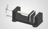
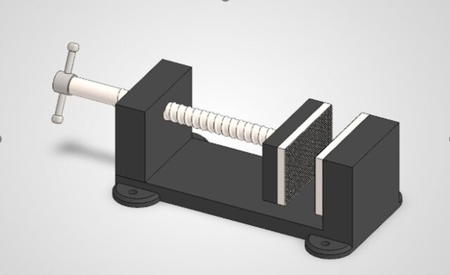
This project showcases an independently designed mechanical bench vise created entirely in SolidWorks, from initial component modeling to final assembly and engineering documentation.
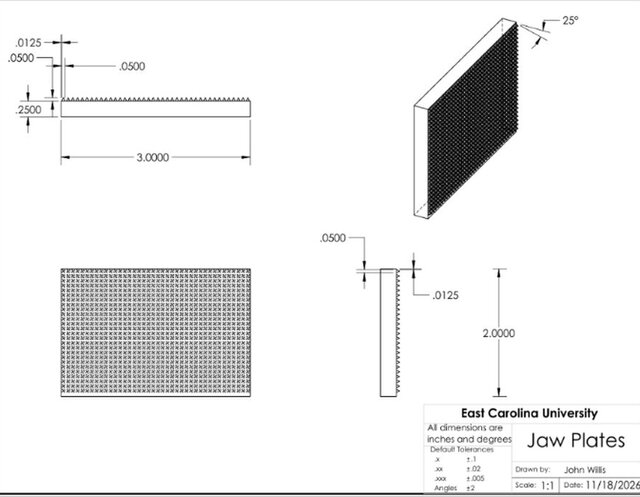
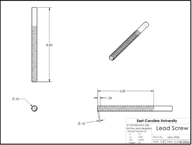
The vise features a lead screw-driven mechanism that moves the front jaw toward the fixed jaw, along with custom-designed gripping plates featuring a patterned surface.
The design process included:
Creating individual mechanical components using parametric 3D modeling
Designing and assembling a lead screw-driven jaw mechanism
Developing custom gripping jaw plates using patterned geometry
Applying SolidWorks assembly mates to constrain components and demonstrate mechanical movement
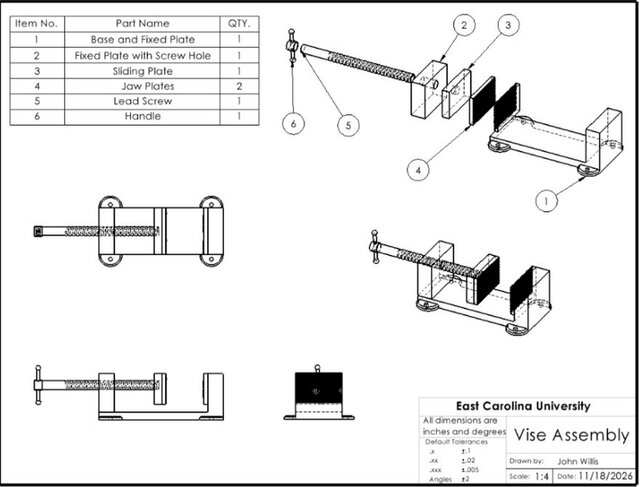
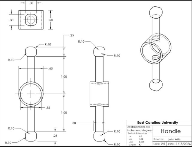
Producing detailed engineering drawings with dimensions and multiple views
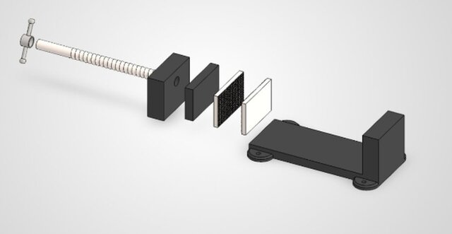
Creating an exploded assembly view to illustrate component relationships
All components were modeled and assembled as part of an independent CAD design project.
Software: SolidWorks
Skills demonstrated: Mechanical design, 3D part modeling, assembly modeling, engineering drawings, parametric modeling, and exploded views.
This is a digital CAD design project and has not undergone physical manufacturing or performance validation.
Published