
Induction Bonder Controller Redesign

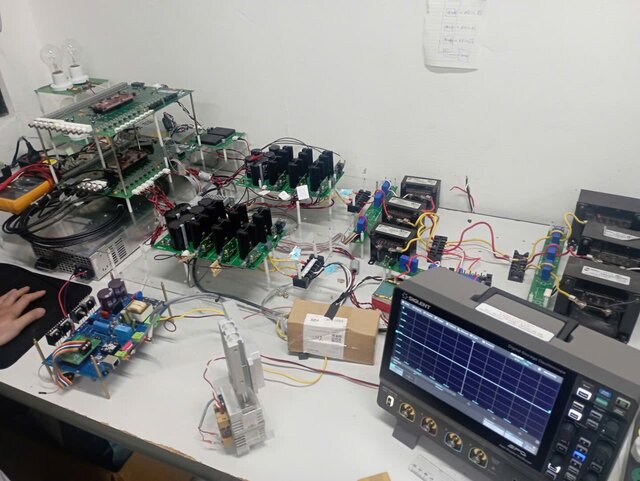
For the last two decades our in-house controller has powered a proprietary induction bonder. The time has come to modernise it. I already know the behaviour I want, but I no longer have an electrical engineer on staff, so I need someone who can translate my functional notes into a production-ready circuit board.
Project goals
• Replace the ageing microprocessor with a current-generation device that gives us more headroom for future firmware and features.
• Fold in several improvements we have identified over years of field use.
Design Overview:
- Built in inductive value check
- Built in temperature controller
- Works on 220VAC single phase
- Digital serial number
- Fast heat up time
- RJ45 connector for communication, use Modbus TCP
- One connector for input power, 3-pin connector which is smaller than the output power
connector
- One connector for output power to weld heads, 3-pin higher amperage and bigger in size for the
input power
- One connector for thermocouple wires
- Ability to easily swap weld controllers (with power off – two 92) 8 position rotary switches)
- Ability to continue cycling machine with an inoperable/missing weld controller (operator
disables controller in machine software- requiring a re-boot)
- Cooling fan built into controllers, runs continuously when power is on.
- Controller can be the same size as existing, smaller height preferably.
- Design within box, no need for card cage.
- Use PID to control heating profile
- Data capture of weld cycle? Can we use the data to improve /adjust parameters?
a. Communicate with the main machine program to provide basic weld controller
information, is there a need to capture per controller the cycle count and/or other info
to be collected in log file or time keys Status
b. Errors
c. status
d. serial number
e. number of cycles
f. on time
g. output on time
h. self-diagnostic test when triggered by PC
Published