




Helical-Blade Sharpener Assembly

Overview
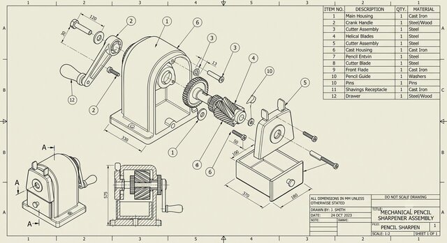
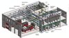
The image is a standard engineering CAD drawing of a manual, hand-cranked pencil sharpener. The drawing features a vintage aesthetic with a beige background and black linework, complete with a border and grid coordinate system (A-C, 1-5).
Visual Elements & Views
The drawing presents the sharpener in three distinct ways:
Exploded Isometric View (Center): This is the primary illustration, showing the sharpener disassembled. It uses dashed projection lines to indicate how the crank handle, gears, helical blades, main housing, and shaving drawer fit together. Bubble callouts with numbers point to each specific part.
Assembled Isometric View (Bottom Left): A smaller representation showing the fully assembled sharpener as it would look on a desk.
Cross-Sectional View (Bottom Middle): A cutaway side view (labeled "A-A") that displays the internal alignment of the gears and the helical cutter mechanism inside the housing.
Bill of Materials (BOM)
In the top right corner, there is a detailed table listing the components corresponding to the numbered bubble callouts in the exploded view. Key parts include:
Item 1: Main Housing (Cast Iron)
Item 2: Crank Handle (Steel/Wood)
Item 4: Helical Blades (Steel)
Item 12: Drawer (Steel/Wood)
Dimensions and Title Block
Dimensions: Various measurements are called out across the drawing in millimeters (e.g., the overall height in the cross-section is marked as 575, and the drawer width is marked as 370).
Title Block (Bottom Right): The official documentation block lists the title as "MECHANICAL PENCIL SHARPENER ASSEMBLY." It notes the drawing was completed by "J.