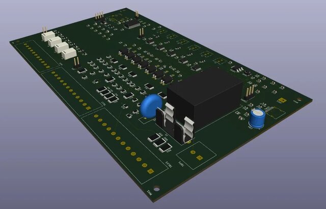
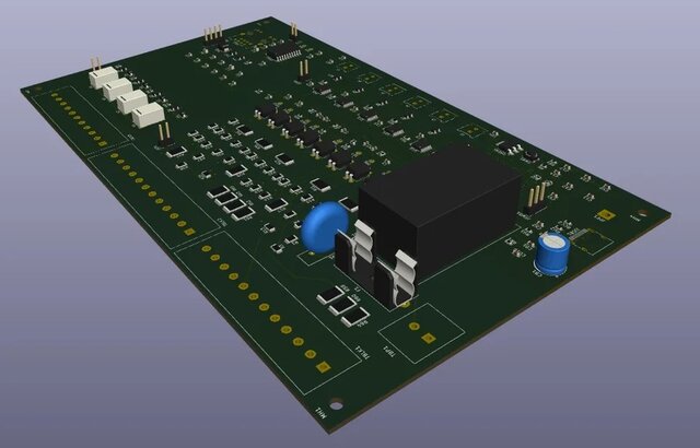


GIM-O: Outdoor Heat-Pump Interface Board (230 V Sensing, Relays, RP2040)

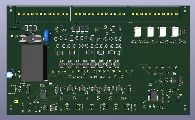
GIM-O is the outdoor board of a two-board interface for a heat pump. It sits in the unit's electrical box on a 35 mm DIN rail and keeps the heat pump's 35 field terminals in their original order, so the existing wiring layout carries over. On top of the terminals it adds the electronics a controller needs to read, imitate and talk to the heat pump: sensing of 230 V signals, relay outputs, programmable resistances that imitate NTC temperature sensors, an RP2040 microcontroller, an isolated RS-485 link to a CAT6 cable and a pass-through for the screen.
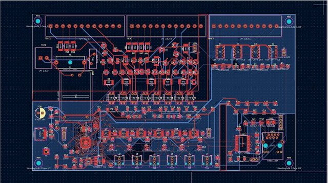
The challenge: fit all of that on a 210 x 125 mm 2-layer board while keeping mains and low-voltage circuits physically apart, keeping the terminal order exactly as specified, and keeping the design manufacturable and assemblable.
What the board does:
- Reads mains signals safely: eight optocouplers, each behind a resistor chain, turn 230 V signals into logic levels across the isolation barrier. The chain components are chosen and placed with their voltage ratings in mind.
- Switches with relays: four double-pole relays with transistor drivers and flyback diodes sit in their own region, away from the logic.
- Imitates temperature sensors: six digital potentiometers (AD5293) set a programmable resistance on six connectors, so the controller can present NTC-style readings.
- Communicates: an RP2040 with USB-C, a SWD header and a BOOTSEL button runs the board. An ADM2587E isolated RS-485 transceiver with TVS protection feeds a shielded RJ45 jack for the CAT6 link.
- Protects the mains entry: a fuse and a varistor protect the 230 V input, and an on-board AC-DC module generates the low-voltage supply.
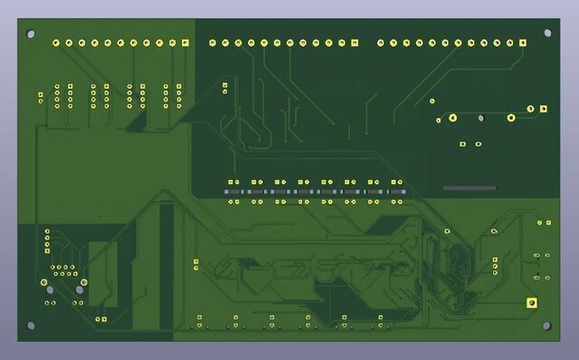
- Keeps mains and low voltage apart: mains-side parts are grouped in their own zone, the logic side has its own ground pour, and a routed isolation slot adds creepage distance beside the isolated transceiver with no copper pour crossing it.
Board data: 210 x 125 mm, 2 layers, 1.6 mm FR4, 1 oz copper, 203 components, 685 pads, 374 vias, 35 field terminals. Routed in KiCad with the design rule check at 0 errors and 0 warnings. Prepared for JLCPCB manufacturing and assembly, with Gerber, drill, BOM, pick-and-place files and a firmware GPIO map as specified in the brief.
This is PCB engineering work, not formal safety certification. Boards that carry mains need an independent review by a qualified person before they are powered.