

ESP32 Printhead Diagnostic Tester: PCB, Firmware and Touchscreen HMI

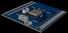
Designed a complete embedded hardware and firmware solution for a client who needed to replace a slow, error-prone manual test with an automated diagnostic instrument. The device checks the health of Epson XP600/ET8550 inkjet printheads by automating the diode-mode continuity test a technician would otherwise do by hand with a multimeter, probe by probe, across up to 58 contact points. It was an end-to-end design: schematic, PCB layout, firmware and a custom touchscreen interface, built around the client's own specification and OEM test data.
The challenge: manual testing means probing dozens of pins in sequence, reading a multimeter and comparing each value against a reference table by eye, which is slow, subjective and easy to get wrong. The client wanted a standalone tester that works with one button press: connect the head, press start, get a clear PASS or FAIL. The available 16-channel multiplexers also did not cover the pin count of both connectors, so the signal architecture had to be engineered around that gap.
My approach:
- Validate before building: I modelled the measurement circuit in LTspice (single diode junction, two junctions in series, open circuit and short circuit) and confirmed every signature matched real multimeter diode-mode behaviour. This exposed the current-limiting requirement early.
- Solve the channel gap in the architecture: I identified the shortfall, worked with the client to add a fourth multiplexer, and redesigned the switching matrix so every pin, including the fixed reference point, has a clean signal path.
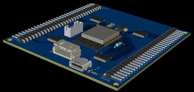
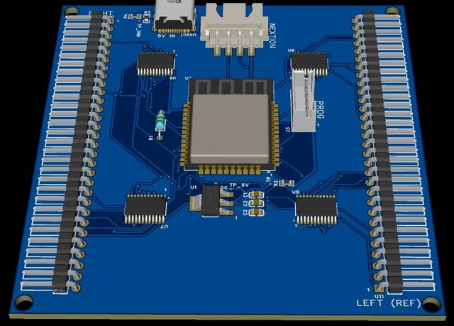
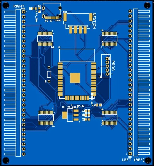
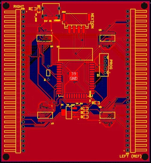
- Build it as a real instrument: a 2-layer, DRC-clean ESP32 board with current-limiting protection so a healthy printhead cannot be damaged during testing, labeled connectors, dedicated test points for bring-up and a USB-C power input.
- Firmware: ESP32 firmware (PlatformIO/Arduino) runs an automated pin sweep across all four multiplexers with a configurable, tolerance-based PASS/FAIL engine and non-volatile MASTER profile storage. Scan one known-good head and every later head is compared against it.
- HMI: a 4-screen Nextion touchscreen shows live per-pin readings, expected versus measured values, deviation and an overall result, with a dedicated screen for capturing and managing the master profile.
- Verification: every pin-to-channel mapping in the firmware was cross-checked line by line against the exported PCB netlist, not just trusted from the schematic.
Deliverables: schematic and PCB design files, Gerbers, bill of materials, commented ESP32 firmware, editable Nextion HMI project, pin and channel mapping table, operating documentation and a validation report.
Status: design phase complete and delivered to the client. The design was verified by simulation, electrical and design rule checks and a firmware build. Physical bring-up and on-hardware testing follow once the board is fabricated.