


Drive Head Assembly

This project shows the design and modeling of a Drive Shaft Assembly developed from 2D drawings and engineering calculations.
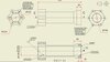
The work began with interpreting a 2D layout and converting it into a complete 3D model using Fusion 360. The drive shaft was modeled according to the specified dimensions and functional requirements. Appropriate bearings were selected based on load considerations and shaft support requirements.
Engineering calculations were performed to ensure the shaft and bearing selection met the design needs. Tolerance and fit analysis was carried out to ensure proper assembly and functionality of the components. Material selection was also considered to ensure the shaft would perform reliably under expected operating conditions.
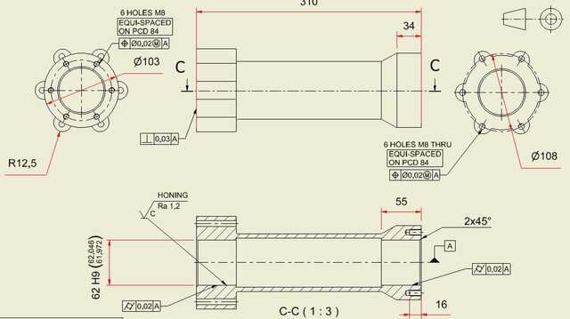
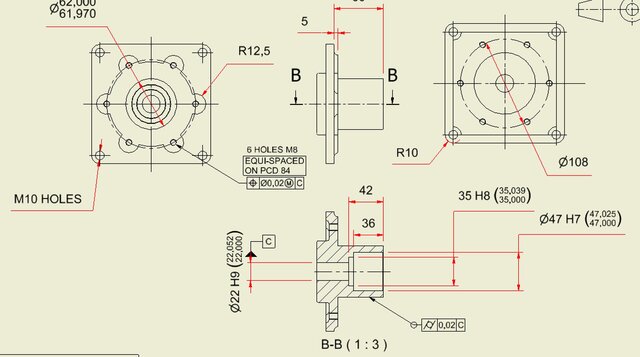
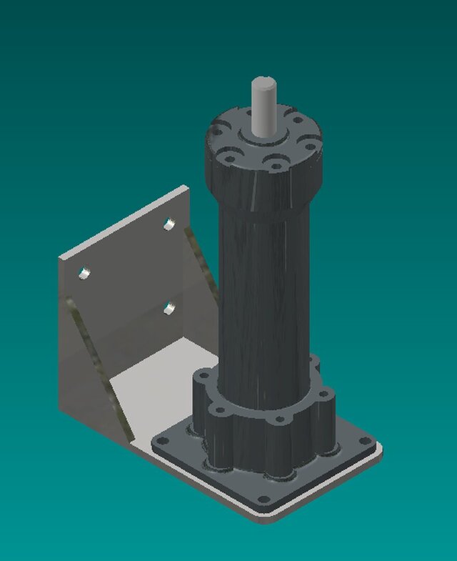
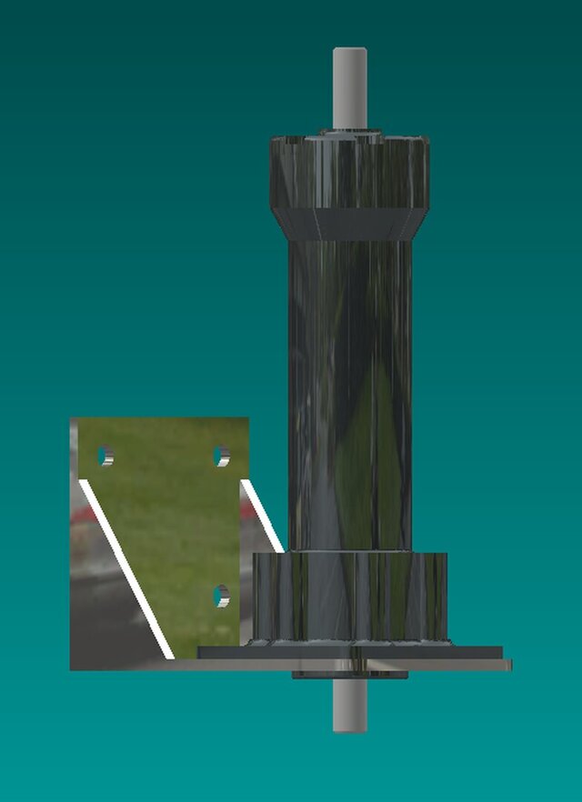
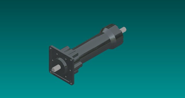
All individual components were modeled separately and then assembled into a full drive shaft assembly in Fusion 360. The images included in this project show:
• The fully modeled drive shaft component
• Individual parts used in the assembly
• The bearing placement and support configuration
• The final 3D assembly created in Fusion 360
• Detailed views highlighting tolerances and fits between components
A technical report was also prepared documenting the calculations, bearing selection, material choice, and tolerance/fit analysis used during the design process.
This project demonstrates skills in CAD modeling, mechanical design, component selection, and technical documentation.