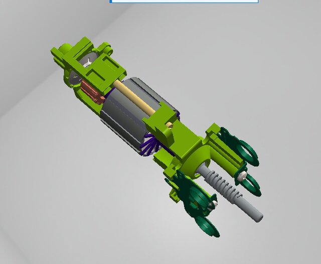
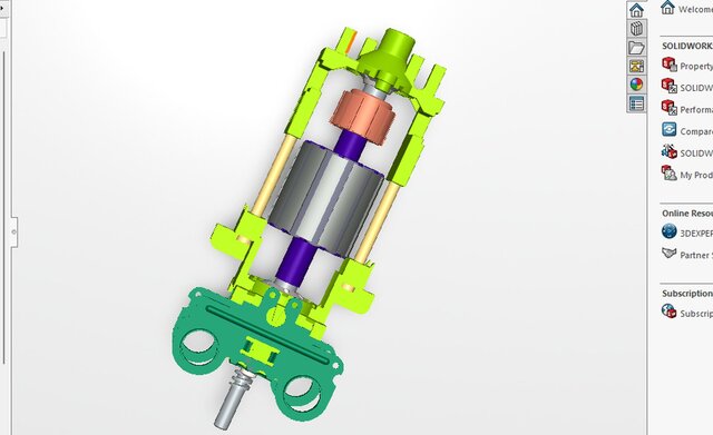


Custom Motorized Kinetic Assembly — Full SolidWorks Simulation

A complete motor/kinetic device designed from
scratch in SolidWorks from individual
component geometry to fully mated dynamic
assembly. Built to production engineering
standards, not just visual presentation.
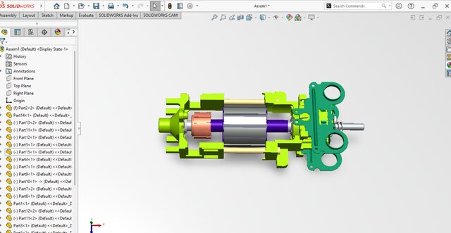
ASSEMBLY SCOPE:
- 15+ unique parts, fully constrained with
SolidWorks Mates
- Zero component interference verified
through collision detection
- Realistic mechanical motion confirmed
via motion study
INTERNAL COMPONENTS DESIGNED:
- Rotor with dynamic clearances for
rotation without housing contact
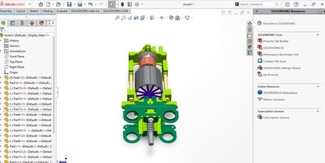
- Commutator segment geometry modeled
for manufacturing and brush contact
accuracy
- Motor Housing split-body design for
assembly access and maintenance
- Shaft, Bearings, End Caps, Brush holders
DESIGN FOR MANUFACTURING (DFM):
- Polymer components: designed for
injection molding uniform wall
thickness, draft angles, no undercuts
- Metal components: optimized for CNC
turning and milling minimized setups,
accessible features
- Clearance fits specified for press-fit
and slip-fit interfaces
MATERIAL DIFFERENTIATION:
Strategic color coding applied to
distinguish Copper windings, Steel
structural components, and Polymer
housings accelerating design review
and production hand-off.
SOFTWARE: SolidWorks
DELIVERABLE TYPE: Full Assembly +
Part Files + Motion Study
Published