

CNC Machined Part Design – NEMA 17 Motor Mount, 6061 Aluminium, 2 Setups & Drawing (PIVOT Concept)

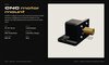
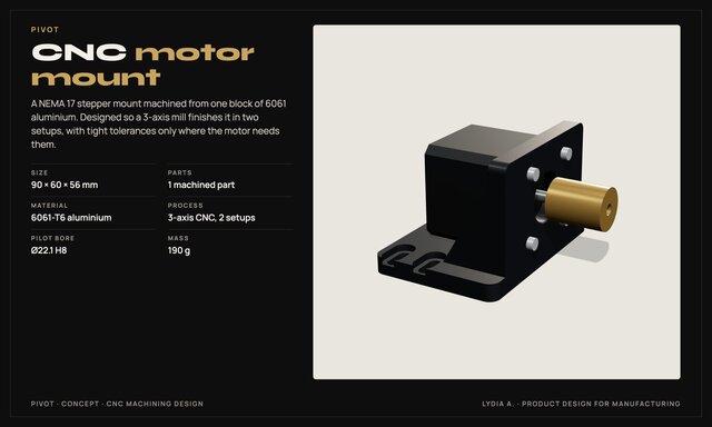
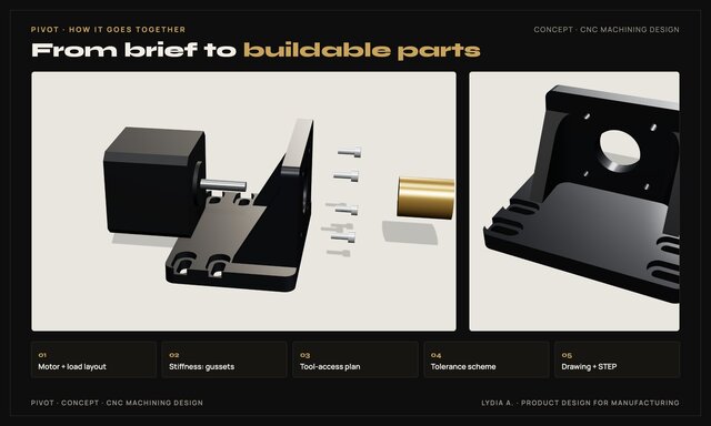
Concept project: a NEMA 17 stepper motor mount machined from one block of 6061 aluminium. It is designed so a 3-axis mill finishes it in two setups, with tight tolerances only where the motor needs them.
What is in the model
- 1 machined part, 90 × 60 × 56 mm, 190 g
- 6061-T6 aluminium, 3-axis CNC, 2 setups
- Ø22.1 H8 pilot bore for the motor
Design for manufacturing (DFM)
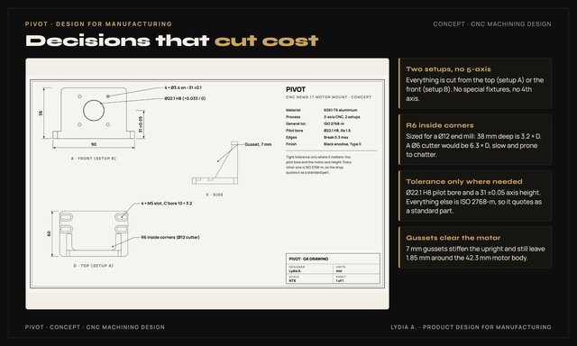
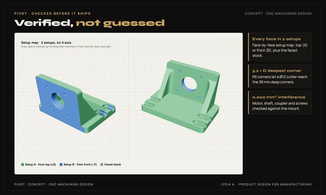
- Two setups, no 5-axis: every face is cut from the top (A) or the front (B)
- R6 inside corners sized for a Ø12 end mill: the 38 mm deep corners are 3.2 × D, not 6.3 × D with a Ø6 cutter
- Tolerance only where needed: Ø22.1 H8 bore and 31 ±0.05 axis height, everything else ISO 2768-m
- 7 mm gussets stiffen the upright and still clear the 42.3 mm motor body by 1.85 mm
Checked in CAD
- Face-by-face setup map: every face reachable in setup A or B
- 0.000 mm³ interference between the mount, motor, shaft, coupler and screws
Included: STEP file and a 2D manufacturing drawing with tolerances.
Services this shows: CNC machining design, machined part design, manufacturing drawings, GD&T and tolerancing, mechanical design, DFM review.