


CAD to CNC Workflow: From 2D Blueprint to 3D Model & Mastercam Toolpaths

This portfolio piece demonstrates a complete engineering and manufacturing workflow, transitioning from a raw technical drawing to a production-ready CNC program.
The project was executed in three distinct phases:
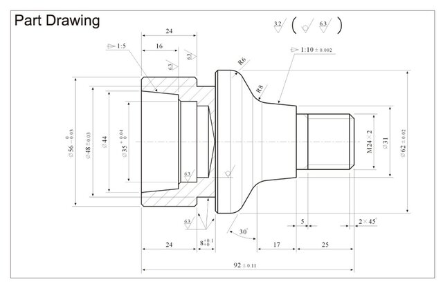
2D Blueprint Interpretation: Analyzed the initial image/blueprint (plano_draw.png) to extract all critical dimensions, geometric specifications, and tolerances required for the part.
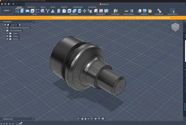
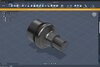
3D Solid Modeling in Fusion 360: Using the 2D data, I recreated the part geometry from scratch, producing a highly precise, clean parametric 3D solid model (part_fus.png).
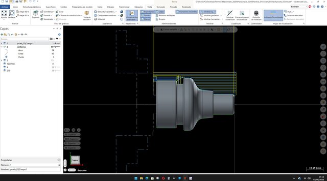
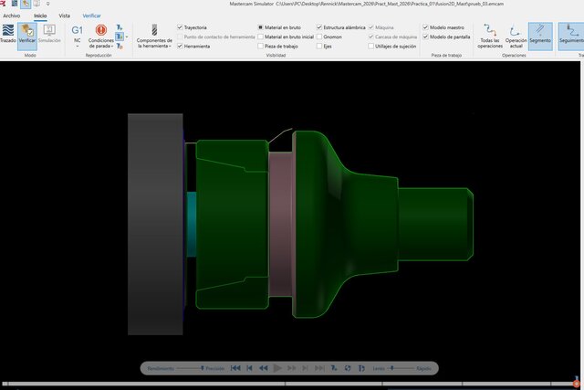
CAM Programming in Mastercam: The 3D model was then imported into Mastercam to design and generate optimized CNC lathe toolpaths (part_draw.png). This step includes detailed operations for roughing, finishing, and custom cycles, fully optimized to minimize machine cycle times and guarantee shop-floor efficiency.
This showcase highlights my ability to seamlessly bridge the gap between initial design concepts, high-precision CAD modeling, and practical, collision-free CNC manufacturing setups.
Published