
basic-part-designs-original

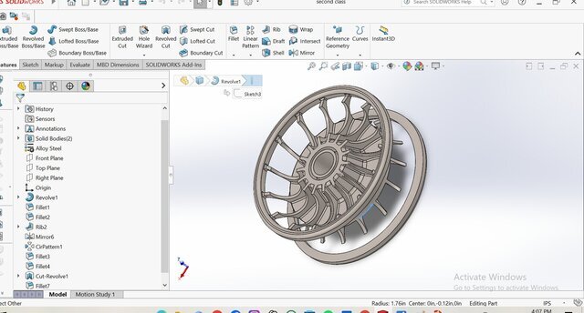
This project represents the foundational transition from 2D engineering graphics to 3D parametric CAD modeling. It showcases a collection of essential mechanical engineering parts designed in SOLIDWORKS, created in direct reference to standard, precise 2D engineering drawing plates.
Key Technical Elements:
2D to 3D Drafting Precision: Accurately translated manual engineering drawing sheets—including title blocks, geometric constructions, and multi-view layouts—into fully dimensional 3D parts.
Orthographic & Sectional Views: Built parts based on rigorous first-angle and third-angle orthographic projections (Front, Top, and Side views), ensuring perfect alignment, correct hidden detail lines, and accurate centerlines.
Feature-Based Parametric Modeling: Utilized core SOLIDWORKS features such as Extruded Boss/Base, Revolved Boss, Extruded Cuts, and precise Fillets/Chamfers to maintain clean, easily editable design trees.
Standard Dimensioning & Fit: Applied standard engineering dimensioning protocols to ensure that wall thicknesses, bored holes, and geometric tolerances strictly match the reference drawing sheets.
Files (9)
License:
CC - Attribution
Learn more