Patented invention needs a brilliant engineer!Blind
in
Invention Design Help
held by
davidsherwood
Last seen:
Contest Ended, Winner(s) have been selected.
-
Open
-
Choosing Finalist
-
Ended
Description:
A Lock mechanism. The off the shelf actuator has a .5 inch throw at 10lbs per pin throw. This throw is vertical and needs to be translated into a 2.5 inch pin throw horizontally. The lock mechanism would be held within a 4 inch by 4 inch wide and 6 inch high maximum protected space. It is for a now patented idea auto-lock for an entire industry of applications. I just need better engineering for the simplest (think mouse trap) type idea. Super simple, cheap, and easy to produce. The best design is for a production video for the licensing company to submit to various interested parties to buy or license out themselves.
Wants:
The simplest and easiest way to translate vertical .5 inch pin throw to 2.5 inches pin throw horizontally in a confined space. Gears? Rails? Sliders ...both? a combo?
Don't Wants:
I don't want a blade lock. I would only like a pin. This 2.5 inch long pin (maybe 1/4 inch to 3/8 inch thick) has to traverse 2.5 inches to deadbolt in the application.
 Prepaid Prize
Entries
1st Winner
#17 Patented invention needs a brilliant engineer!
by CDdesignSTUDIO
Hidden design
Sep 1, 2022 23:12
#16 Patented invention needs a brilliant engineer!
by CDdesignSTUDIO
Hidden design
Sep 1, 2022 21:06
#13 Patented invention needs a brilliant engineer!
by CDdesignSTUDIO
Hidden design
Download Files
Sep 1, 2022 3:53
#30 actuator mechanism - By Adriano Ordoz Barissa
by Adriano Ordoz Barissa
Hidden design
Sep 15, 2022 19:27
#33 Patented invention needs a brilliant engineer 2
by Vimalgeorge10
Hidden design
Download Files
- IGES / IGS File Design — Patented invention needs a brilliant engineer 2
- STEP/STP 3D Modeling — Patented invention needs a brilliant engineer 2
- IGES / IGS File Design — Patented invention needs a brilliant engineer 2 actuated
- STEP/STP 3D Modeling — Patented invention needs a brilliant engineer 2 actuated
- Rendering Images — Patented invention needs a brilliant engineer 2
- Rendering Images — Patented invention needs a brilliant engineer 2 Actuated
- Rendering Images — Patented invention needs a brilliant engineer 2
Sep 19, 2022 19:53
#34 actuator 2- By Adriano Ordoz Barissa
by Adriano Ordoz Barissa
Hidden design
Download Files
Sep 21, 2022 13:58
#35 Complete Design Lock - By Adriano Barissa
by Adriano Ordoz Barissa
Hidden design
Download Files
Sep 21, 2022 14:01
#36 Final Lock - By Adriano Barissa
by Adriano Ordoz Barissa
Hidden design
Download Files
- gif — Lock 001 1
- pdf — REV1 - Lock 001
- pdf — Machined components
- pdf — Main Support - Sheet steel bent part
- pdf — Drive arm - Bent sheet steel part
- Autodesk DWG TrueConvert — Drive arm - Bent sheet steel part
- Autodesk DWG TrueConvert — Main Support - Sheet steel bent part
- SolidWorks — Suporte Principal
- SolidWorks — Bra o de Movimenta o
- SolidWorks — Pino
- STEP/STP 3D Modeling — Lock 002
- SolidWorks — Arruela de apoio
- SolidWorks — Bucha 1
- SolidWorks — Pino 1
- SolidWorks — Pino 2
- SolidWorks — Pino 3
- png — render 01
- png — render 02
Sep 21, 2022 14:09
#37 Door Lock R0 Pin Type ( 2 x 2 x 5 cin)
by Indranil_Routh
Hidden design
Download Files
Sep 21, 2022 20:07
#40 Patented invention needs a brilliant engineer!
by sherifelsheikh
Hidden design
Download Files
- — System Animation
- — System Animation-2
- jpg — Lock Mechanism Final -01
- jpg — Lock Mechanism Final -02
- jpg — Lock Mechanism Final -03
- jpg — Lock Mechanism Final -04
- jpg — Lock Mechanism Final -05
- jpg — Lock Mechanism Final -06
- jpg — Lock Mechanism Final -07
- jpg — Lock Mechanism Final -08
- jpg — Lock Mechanism Final -09
- jpg — Lock Mechanism Final -010
Sep 24, 2022 18:52
#44 Patented invention needs a brilliant engineer 3
by Vimalgeorge10
Hidden design
Download Files
- Microsoft PowerPoint — Patented Invention Needs A Brilliant Engineer 3 Design Specs
- STEP/STP 3D Modeling — Patented invention needs a brilliant engineer 3 Retracted
- STEP/STP 3D Modeling — Patented invention needs a brilliant engineer 3 Actuated
- IGES / IGS File Design — Patented invention needs a brilliant engineer 3 Retracted
- IGES / IGS File Design — Patented invention needs a brilliant engineer 3 Actuated
- 3D Technical Animation — Patented invention needs a brilliant engineer 3 animation
- 3D Technical Animation — Patented invention needs a brilliant engineer 3 animation actual speed
- 3D Technical Animation — Patented invention needs a brilliant engineer 3 Assembly
- Rendering Images — 1
- Rendering Images — 2
- Rendering Images — 3
- Rendering Images — 4
- Rendering Images — 5
- Rendering Images — Patented invention needs a brilliant engineer 3
Sep 25, 2022 16:10
#11 Patented invention needs a brilliant engineer!
by CDdesignSTUDIO
Hidden design
Download Files
Aug 31, 2022 3:39
#3 Patented invention(Lock)
by MechanicalCADdesigner
Hidden design
Download Files
Aug 29, 2022 14:55
#4 Patented invention needs a brilliant engineer!
by CDdesignSTUDIO
Hidden design
Download Files
Aug 29, 2022 23:04
#5 Patented invention needs a brilliant engineer!
by hariono
Hidden design
Download Files
Aug 30, 2022 1:15
#6 Patented invention needs a brilliant engineer!
by CDdesignSTUDIO
Hidden design
Download Files
Aug 30, 2022 7:15
#7 Simulation_Simplified concept_1
by Fandu_DesignStudio
Hidden design
Download Files
Aug 30, 2022 18:34
#8 Patented invention needs a brilliant engineer!
by CDdesignSTUDIO
Hidden design
Download Files
Aug 30, 2022 18:39
#10 Patented invention needs a brilliant engineer!
by CDdesignSTUDIO
Hidden design
Download Files
Aug 31, 2022 2:42
#15 Patented invention needs a brilliant engineer!
by CDdesignSTUDIO
Hidden design
Download Files
Sep 1, 2022 20:43
#21 Concept 1
by Vimalgeorge10
Hidden design
Download Files
- STEP/STP 3D Modeling — Patented invention needs a brilliant engineer 1 unactuated representation
- STEP/STP 3D Modeling — Patented invention needs a brilliant engineer actuated representation
- Autodesk Fusion 360 — Patented invention needs a brilliant engineer
- Rendering Images — Patented invention needs a brilliant engineer 1
- Rendering Images — Patented invention needs a brilliant engineer 1
- Rendering Images — Fully actuated representation
- Rendering Images — Un-actuated representation
Sep 3, 2022 20:47
#1 Patented invention needs a brilliant engineer!
by CDdesignSTUDIO
Hidden design
Download Files
Aug 29, 2022 1:48
Discussion
who is the winner ?

Hi David..I can see,you have that mechanism in 3D.. can you share that with us ?

Why should a person participate when there is only one prize? The likelihood that at least some part of a participant's working time will be paid is minimized. It is always better for all prizes to be AT LEAST three. I personally do not participate in a competition with one prize. Firstly, it is unreasonable and secondly, such an attitude towards potential participants is insulting. "Come, as many people as you can, work on my problem, and I will pay only one." No thanks.

It's a 2.5 inch pin that will be actuated thousands of times and be easy to replace the actuator when it wears out.

You have been online 2 hours ago and you haven't answered my question, honestly I am not wasting my time here any more. Go and have fun with these desperate idiots.
Please reply, if you intend to make your contest worth while.
By the term "deadlock" does it means that it is a one time emergency lock that needs to be manually unlocked?
By the term "deadlock" does it means that it is a one time emergency lock that needs to be manually unlocked?
By the term "deadlock" does it means that it is a one time emergency lock that needs to be manually unlocked?

Would you please clarify if the volume 4*4*6 inches is the allowable space after the linear actuator extends or before? Thanks.
The two pics you shared recently are un available
Just answer this question:
By the term "deadlock" does it means that it is a one time emergency lock that needs to be manually unlocked?
By the term "deadlock" does it means that it is a one time emergency lock that needs to be manually unlocked?
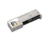 This a dead bolt lock. It must cross the first threshold and then cross the second threshold 2" further along the pin throw. A design that is higher (longer) than 6" will not work in this application. Super compact, super simple, easy to swap out motor, ...seen some killer stuff from y'all.
I cannot edit the original contest with better details sorry,
I need the lock and mechanism to be as small and compact as possible. The lock mechanism as well as the actuator have to fit in the volume. so something 4x4x6 inches would be good, 3x3x6 would be better, and 2x2.5x6 would be best!
The actuator ...like these ones, below, super dependable and cheap! Easy to swap out and replace, multiple actuators will be working in tandem, And that is why I am needing the simplest mechanical system an engineer can come up with.
Your well designed bracket or housing would encapsulate hopefully the smallest size possible (2x2.5x6) ....be easy to remove to swap out the actuator, or better just have a way of replacing the actuator itself without removing the housing. Access would be from the back or side of the mechanism, The actuators I am super trying to use are 1" x 2.5" wide, and 5.5" long when open. 5" when closed . The actuator can be used sideways also (2.5") ...up to you,
Here are a bunch from aliexpress
https://campaign.aliexpress.com/wow/gcp/pc-ppc-lp/index?UTABTest=aliabtest310560_422162&_randl_currency=CAD&_randl_shipto=CA&src=google&src=google&albch=shopping&acnt=631-313-3945&slnk=&plac=&mtctp=&albbt=Google_7_shopping&albagn=888888&isSmbActive=false&isSmbAutoCall=false&needSmbHouyi=false&albcp=17303965158&albag=139800743191&trgt=1657595421766&crea=en1005003027802585&netw=u&device=c&albpg=1657595421766&albpd=en1005003027802585&gclid=CjwKCAjwx7GYBhB7EiwA0d8oe6npgAe1Oko9eyQAVOrzlLPTvUHyj8qkxM92Rlbzlz1bu8svPnwruhoCF-QQAvD_BwE&gclsrc=aw.ds&aff_fcid=c2cd6adc0f984c42b2fe9eb2c1820589-1661819701986-06325-UneMJZVf&aff_fsk=UneMJZVf&aff_platform=aaf&sk=UneMJZVf&aff_trace_key=c2cd6adc0f984c42b2fe9eb2c1820589-1661819701986-06325-UneMJZVf&terminal_id=652225368f074577bd3da73fc287d6ec&wh_weex=true&_immersiveMode=true&bt_src=ppc_direct_lp&scenario=pcBridgePPC&productId=1005003027802585&OLP=1083300108_f_group1&o_s_id=1083300108
I also have the same question as @richards. Would you mind dimensioning the enclosure so we have a clear understanding of the space corresponding to the orientation. Thanks.
OK, long story short: Workspace: 4x4x6 inch; Input: 0.5 inch vertical and output "Drum Roll": 2.5 inch horizontal
The 2 questions I have is:
1- By the term "deadlock" does it means that it is a one time emergency lock that needs to be manually unlocked?
2- If you have that linear actuator on Amazon, why do you want to recreate the wheel? DOes it doesn't fir in the 4x4x6 size?
The 2 questions I have is:
1- By the term "deadlock" does it means that it is a one time emergency lock that needs to be manually unlocked?
2- If you have that linear actuator on Amazon, why do you want to recreate the wheel? DOes it doesn't fir in the 4x4x6 size?

Please could you clarify the orientation of the 4" x 4" x 6" maximum enclosure volume. Which is the 6" 'height' dimension: is it parallel to the actuator throw axis or orthogonal to both the actuator and locking pin axes?
Does the actuator have to fit inside this volume as well as the mechanism? If so, can you give some basic overall dimensions of the actuator.
Thanks
Does the actuator have to fit inside this volume as well as the mechanism? If so, can you give some basic overall dimensions of the actuator.
Thanks
This an example of the actuator we want to use. An off the shelf very cheap and reliable generic motor with a .5 inch throw. 12V. To be mounted perpendicular to the 2.5 to 3 inch lock pin. So the pin would be extended at least 2.5 inches out of the enclosure in the lock position. And retreat 2.5 inches into the 4x4x6 enclosure when unlocked.
This is not for a working prototype so the power of the motor doesn't matter. It is just to create the simplest 3d model that can be shown to work in 3D. A mounting bracket for the system would also be necessary. Maybe a rack and pinion system? Or levers? Both? Just as simple as conceivably possible, and it only has to be shown to work in the 3d model.
https://www.amazon.ca/Universal-Power-Actuator-12-Volt-Motor/dp/B00CZBQCR2/ref=sr_1_2_sspa?keywords=auto+lock+actuator&qid=1661718234&sr=8-2-spons&psc=1

Are you asking to design a mechanism for displacing 2.5 in a lock pin using a linear actuator with .5 inch stroke and 10 lbs force? Additionally: the linear actuator is to be installed in a 4 x 4 x 6 inch space.
My first question is: Why using a linear actuator for driving the pin? Is it ok if we use a rotary actuator?
Another question: Is 2 lbs (10 x.5 /2.5) the required force? For a locking mechanism, seems a lot
My first question is: Why using a linear actuator for driving the pin? Is it ok if we use a rotary actuator?
Another question: Is 2 lbs (10 x.5 /2.5) the required force? For a locking mechanism, seems a lot
All I have are those 3d screenshots. neither of those designs will work but do give a picture of the actuator with the .5 inch pin throw and in general how it should work.

Hi David..I can see,you have that mechanism in 3D.. can you share that with us ?
Similar Contests on Cad Crowd
Wheelie Bin Lid Lifter
I’m looking for an experienced CAD designer to take the current design of my patent pending Wheelie Bin Lid Lifter and make it aesthetically better. I would also like them to develop a 3D model design/animation showing that it works and create the CAD drawings to suit So that I can take it to a manufacturer and they can make me a working prototype. Please see the attached images and video of my working prototype.
Utility knife
I am looking for a utility knife design where the blade can go from cutting, to scraping, without removing the blade from the handle.
The knife should preform like a normal utility knife when cutting. Then the blade edge would have to be fully exposed, and locked into a "T" shape with the handle, allowing the knife to scrape a flat surface.
The blade should be the standard, trapezoidal utility blade.
The blade would have to fold or slide into the handle when not in use.
Novel Naval Architecture and Retrofit Electric Marine Propulsion Systems
At Fluidity Marine, our mission is to develop sustainable and eco-friendly marine technologies that push the boundaries of performance, efficiency, and environmental responsibility. We strive to revolutionize the marine industry by creating innovative solutions that reduce environmental impact while improving performance and safety. Our goal is to lead the way towards a more sustainable future for the marine industry and promote responsible stewardship of our oceans and waterways.
For our initial fundraising efforts, we require some conceptual artwork of novel and theoretical designs for 3D Printed Hull designs across an array of hull types (Pontoon, Semi-Displacement, and Planing Hulls) all with modular electric motors and water jet, impeller based and rudderless propulsion. Dynamically deployed hydrofoil systems with integrated impellor jet systems are encouraged.
We have basic sketches of an array of designs attached to the project, but would appreciate extrapolation and creativity in so much as the designs are either:
1) Completely novel hull designs only possible with 3D printed manufacturing
2) Integrated flat nozzle water jet arrays without rudders that navigate based on flow control of jets on one side or the other.
3) Aftermarket Retrofit devices that can be attached to existing hulls to convert traditional hulls to electric propulsion.
4) Foiling Impeller Systems that extend on-demand from the hulls (integrated and aftermarket)
5) Solar and Wind generated energy systems integrated into the shade structures of the boats. Particularly Flexible Solar Cloth as Biminis, Gorlov Helical Turbines mounted horizontally on shade structures underneath rigid solar shade structures above them.
6) Automated Solar and Wind powered barges, docks, and other marine support structures.
Seed Deck Investment pitch attached with sketches for additional context.
African Food Packaging Machine (Manually operated)
I'm looking for someone who a can conceptualize, design, make 3D model and make animation of the packaging machine for an African traditional food packing method as shown in attached video. In which, for a single cycle we just have to put the leaves one on another in machine and feed the food somewhere so that it can be laid on to the leaves and then rest of the packaging process be carried out by machine itself while operated manually. The final packaging should look as close to the original hand packaging as possible. The machine should be manually operated and not electric one.
Accessory Clip for Glasses
I'm looking to create a series of fun accessories that can clip to the front of glasses or sunglasses.
In this first design, the priority deliverable is the clip system to attach to the glasses. I am envisioning something like one or two S clip fasteners that would attach to either the nose bridge or each lens’ frame. The fastener would work similar to the way a money clip can be flexibly opened to insert cash and then returns to a snug resting position. See attached rough illustration for what I am envisioning.
I am open to alternative fastener designs when the designer proposes a better system for connecting the accessory to the glasses. I am hoping that the fastener can work with both thicker plastic glasses, as well as thinner wire frame glasses.
The accessory I would like to develop in this contest is a unicorn horn. It should be connected in the design to the fastener, so the end design is one, single piece.
Adam-maulana91
Designer